How to Choose an RS-485 Cable: Impedance, Capacitance, Gauge and Distance
RS-485 cable selection: 120 Ω impedance, low capacitance, twisted pairs and shielding, distance vs baud rate, Modbus, PROFIBUS and CAN differences, what to order.

An RS-485 cable is a twisted-pair cable with a characteristic impedance of 120 Ω, the lowest capacitance the budget allows, and, in a plant, an overall foil-and-braid shield. Those three properties, together with the conductor gauge, decide how far and how fast a Modbus RTU or other RS-485 bus can run before the data turns into the electrical equivalent of a phone call from inside a tunnel. This guide explains what each parameter does, how far a bus can run at each data rate, why a PVC control cable is not a substitute for a 120 Ω cable, and what to write on the purchase order. It covers cable selection only; termination and grounding follow the instructions of the device manufacturer.
TEBAOFLEX ENGINEERING ROUTE
Not sure which construction your bus needs?
Send the bus length, baud rate, node count and environment to the TEBAOFLEX cable engineering service. You get back a construction proposal for a 120 Ω RS-485 data bus cable together with the datasheet for the construction offered.
What does an RS-485 cable have to do?
An RS-485 cable carries a differential signal between up to 32 unit loads on one twisted pair terminated at both ends with 120 Ω. TIA/EIA-485-A defines the driver and receiver electronics; the TI RS-485 Design Guide (SLLA272D) gives the practical limits as 4,000 ft (about 1,200 m) at 100 kbps and 40 ft at 10 Mbps.
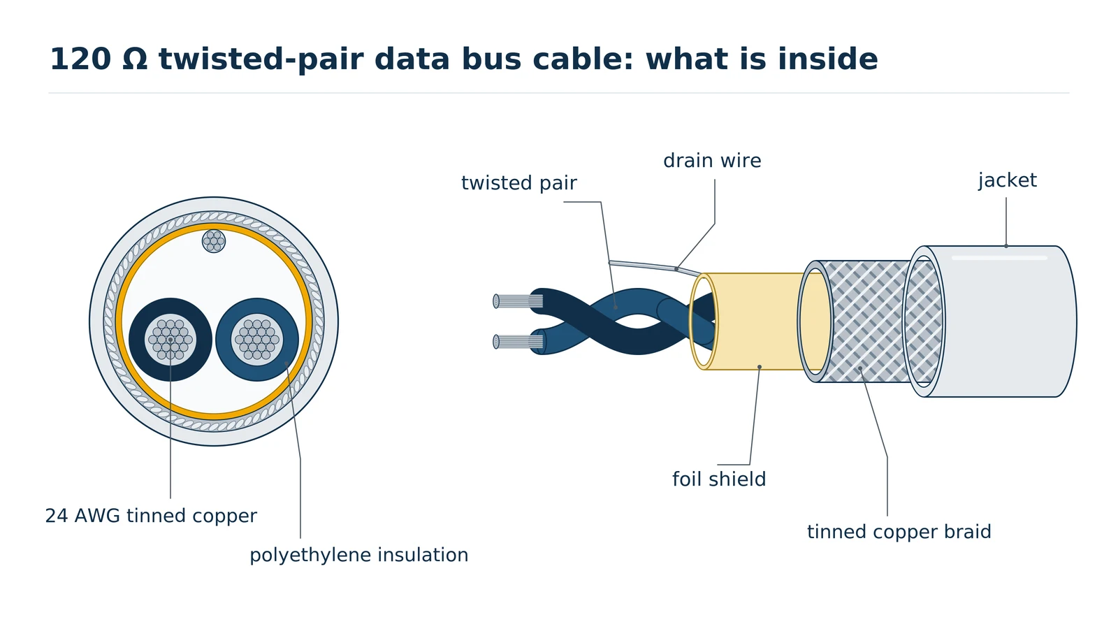
The standard defines the electronics, not the cable. What it asks of the cable follows from the physics of a differential line: the two conductors must be twisted so that interference hits both equally and cancels at the receiver, the line must present the same impedance the terminators are built for, and it must not load each bit edge with so much capacitance that the driver runs out of time. The design guide describes the typical industrial RS-485 cable as a sheathed, unshielded twisted pair with a characteristic impedance of 120 Ω and 22–24 AWG conductors; most plant installations add a shield on top of that, for reasons covered below.
Why must the characteristic impedance be 120 Ω?
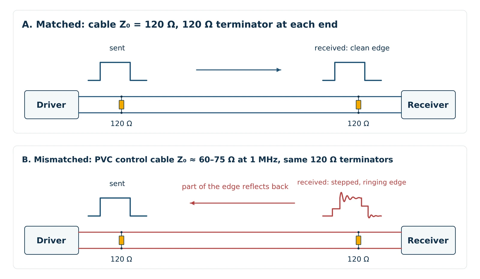
Characteristic impedance must match the 120 Ω termination resistors fitted at each end of an RS-485 bus. A mismatch reflects part of every signal edge back along the line, where it adds to or subtracts from the next bit. Industrial RS-485 cables are therefore specified at 120 Ω nominal, typically ±10 %, as the Belden 9841 datasheet (2013) shows.
Impedance is a property of the cable’s geometry and insulation, not of its conductor size. Two conductors spaced by a thin, low-permittivity insulation such as polyethylene give a high impedance; the same conductors packed closely in PVC give a low one. That is why a general-purpose PVC screened twisted-pair control cable, however good it is at carrying 24 V DC signals, measures nowhere near 120 Ω: the Lapp UNITRONIC LiYCY (TP) datasheet 0035131 lists 76 Ω at 1 MHz for the 0.14 mm² size and 55 Ω for the 1.5 mm² size, with 62–93 Ω at 100 kHz (Lapp data, retrieved September 2026). The mismatch matters most on the fast edges of each bit, so a short link at 9,600 baud often tolerates it and the same cable fails at 200 m or at 115.2 kbaud. Figure 1 shows the difference.
How much capacitance is acceptable in an RS-485 cable?
Lower capacitance is better for RS-485 at every length and baud rate. Installer guidance converges on 60 pF/m or less between conductors (ModbusCloud RS485 cable selection guide, 2026). Capacitance and length together set the electrical load the driver must charge on every bit edge, so a high-capacitance cable shortens the usable bus at any given baud rate.
Capacitance is the cable’s habit of hoarding charge, a little like the colleague who holds every reply until Friday: the bus still works, just later than the receiver expected. The datasheet figure to compare is conductor-to-conductor capacitance, usually quoted in pF/m or pF/ft at 1 kHz. Table 1 puts the three cable families a buyer is likely to meet side by side. The gap is not subtle: a dedicated RS-485 cable with polyethylene insulation sits around 42 pF/m, a data-grade Ethernet pair around 50 pF/m, and a PVC control cable at two to three times that.
| Cable family | Insulation | Capacitance, conductor to conductor | Characteristic impedance | Published source |
|---|---|---|---|---|
| Dedicated 120 Ω RS-485 cable (Belden 9841 class) | Polyethylene | 42.0 pF/m (12.8 pF/ft) | 120 Ω nominal | Belden 9841 metric datasheet, 2013 |
| CAT5e / CAT6 data cable | Polyethylene or polyolefin | About 50 pF/m | 100 Ω | ModbusCloud, 2026 |
| PVC screened twisted-pair control cable (LiYCY (TP) type) | PVC | 95–135 pF/m depending on cross-section | 55–76 Ω at ≥ 1 MHz | Lapp UNITRONIC LiYCY (TP) datasheet 0035131, retrieved September 2026 |
Values are the manufacturers’ published nominal figures for the products named and are quoted for comparison only.
What wire gauge does an RS-485 cable need?
24 AWG (0.22 mm²) is the common conductor size for RS-485 cables and covers most low-baud buses up to 1,200 m. 22 AWG (0.34 mm²) is chosen for long runs, high ambient temperatures, or a pair that also carries device power. The TI design guide describes 22–24 AWG twisted pair as typical.
Gauge decides DC resistance, and resistance decides how much of the driver’s voltage swing survives to the far end once the terminators are drawing current. It also sets how much voltage is lost if the pair doubles as a supply for field devices, which is common on meter and sensor buses. The conversion between AWG and mm² is a frequent source of ordering errors, so state both on the order: 24 AWG is 0.205 mm² by the AWG formula and is usually listed as 0.22 or 0.25 mm² in European catalogs, and 22 AWG is 0.326 mm², listed as 0.34 mm². For any other gauge, see our AWG to mm² converter and wire gauge chart.
| Size | Nominal area | Conductor resistance at 20 °C, published | Choose this when |
|---|---|---|---|
| RS-485 cable 24 AWG | 0.22–0.25 mm² | 78.7 Ω/km nominal (Belden 9841, 7×32 tinned copper); 94.2 Ω/km max for 0.23 mm² (Lapp LiYCY (TP) A datasheet, 2026) | Standard bus runs at 9.6–115.2 kbaud up to about 1,200 m; compact cable trays and glands |
| RS-485 cable 22 AWG | 0.34 mm² | 59.4 Ω/km max (Lapp, 0.34 mm²) | Runs near the length limit, elevated ambient temperature, or a pair that also feeds device power |
| Signal cable 20 AWG | 0.5 mm² | 36.7 Ω/km max (Lapp, 0.5 mm²) | Power-and-data hybrids where the supply current, not the signal, sets the conductor size |
Resistance figures are taken from the named manufacturers’ published datasheets; the conductor resistance of a TEBAOFLEX construction is stated on its own datasheet.
How far can an RS-485 cable run?
RS-485 runs about 1,200 m (4,000 ft) at up to 100 kbps on 22–24 AWG, 120 Ω twisted-pair cable, according to the TI RS-485 Design Guide. Above 100 kbps the usable length falls with the data rate, to about 12 m (40 ft) at 10 Mbps. Modbus RTU at 9,600 or 19,200 baud sits inside the 1,200 m region.
Every bus has a Monday-morning limit, and for RS-485 it is the point where cable attenuation and capacitance have rounded the bit edges so far that the receiver can no longer tell a one from a zero. The TI guide places that point, for 22 AWG 120 Ω cable, at roughly 1,200 m, where the line has cost the signal about 6 dB. Table 3 gives the working figures. The PROFIBUS DP rows use the segment lengths from IEC 61158-2 for Type A cable, which shares the RS-485 physical layer but specifies a 150 Ω cable, so treat them as an indication of how quickly length collapses at megabit rates rather than as RS-485 limits.
| Data rate | Usable length | Basis |
|---|---|---|
| Up to 100 kbps (Modbus RTU 9.6–115.2 kbaud) | About 1,200 m (4,000 ft) | TI SLLA272D, 22–24 AWG, 120 Ω cable, terminated both ends |
| 187.5 kbit/s | 1,000 m | PROFIBUS DP segment limit, IEC 61158-2 Type A cable (indicative) |
| 500 kbit/s | 400 m | PROFIBUS DP segment limit (indicative) |
| 1.5 Mbit/s | 200 m | PROFIBUS DP segment limit (indicative) |
| 3–12 Mbit/s | 100 m | PROFIBUS DP segment limit (indicative) |
| 10 Mbps | About 12 m (40 ft) | TI SLLA272D |
PROFIBUS figures as summarised by SCADA Protocols, PROFIBUS cable types A, B and C, retrieved September 2026. All lengths assume correct termination and a cable that meets the specification; stubs, unterminated branches and mismatched cable shorten them.
Does RS-485 need a shielded cable?
RS-485 does not require a shield electrically: TIA/EIA-485-A works over unshielded twisted pair, and the TI design guide describes UTP as typical. In industrial plants an overall foil with a tinned copper braid and drain wire is the normal choice, because it suppresses capacitive coupling from nearby power and drive cables. For when a tinned conductor or braid is worth specifying, see our copper conductor guide. Connect the shield as the device manufacturer specifies.
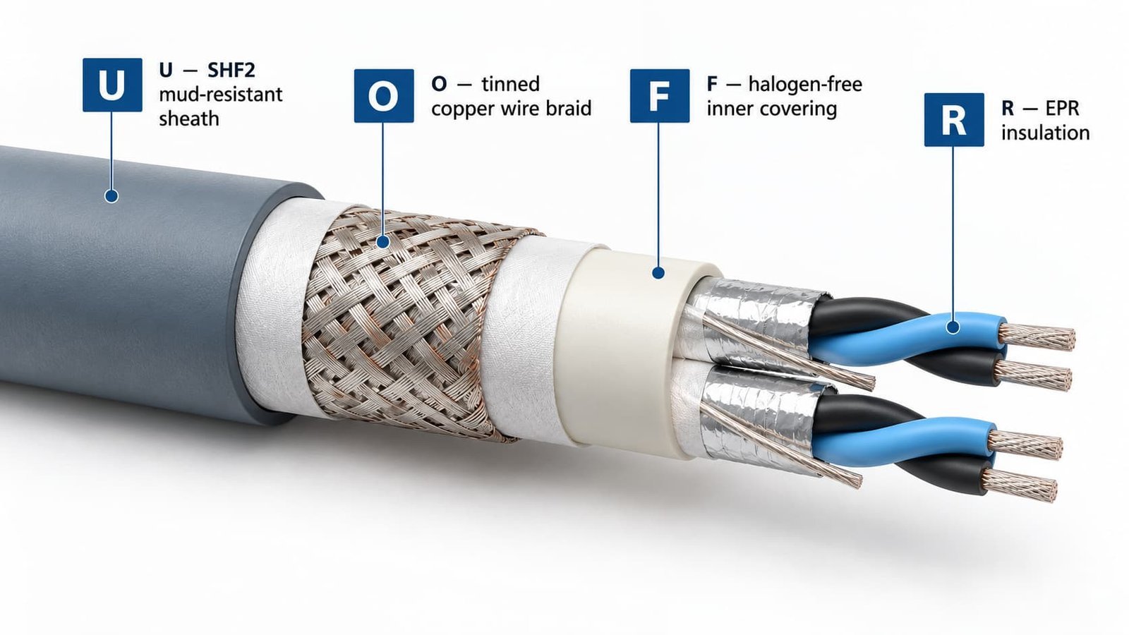
Twisting handles magnetically induced noise, because both conductors pick up the same disturbance and the receiver subtracts it. Capacitively coupled noise from a parallel 400 V motor cable is a different animal, and the foil is what stops it. The braid adds mechanical robustness and a low-resistance path for the drain wire; the Belden 9841 construction, to take one published example, uses a 100 % foil with a 90 % tinned copper braid and a 24 AWG drain wire. Where the bus shares a tray with variable-speed drives, the shield is not optional in practice, whatever the standard says.
Two-wire or four-wire RS-485: one pair or two?
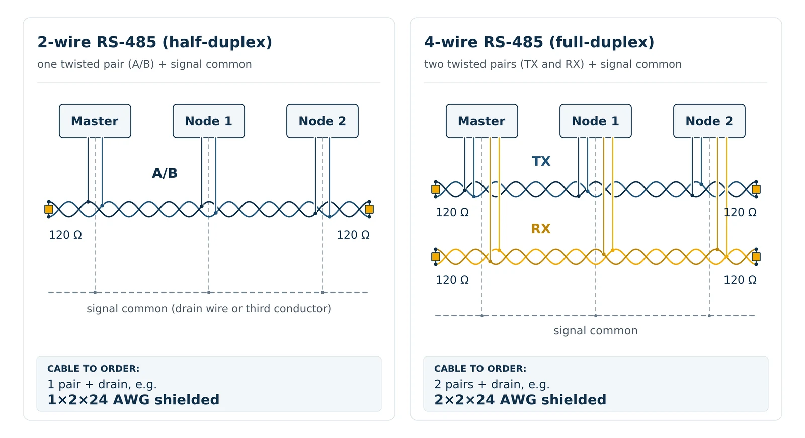
Two-wire (half-duplex) RS-485 uses one twisted pair plus a signal common conductor; four-wire (full-duplex) RS-485 uses two twisted pairs plus common. Choose a one-pair shielded cable with a drain wire or third conductor for half-duplex Modbus RTU and BACnet MS/TP, and a two-pair cable for full-duplex links or a spare pair.
The signal common is the conductor most often forgotten on the order. TIA/EIA-485-A receivers tolerate a common-mode range of −7 V to +12 V, and without a common reference between nodes that range is easily exceeded when devices sit on different earth potentials. On a shielded cable the drain wire can serve as the common; on an unshielded cable a third conductor is needed. Figure 2 shows the two arrangements and the cable each one needs.
Modbus RTU, PROFIBUS DP, CAN bus and DeviceNet: is it the same cable?
Modbus RTU, CAN bus and DeviceNet all specify a 120 Ω cable, but PROFIBUS DP Type A specifies 150 Ω nominal (135–165 Ω at 3–20 MHz) with capacitance of 30 pF/m or less, so a PROFIBUS cable is not interchangeable with a generic RS-485 cable. Check the protocol’s cable specification before ordering, not just the connector.
Table 4 collects the cable requirements of the four buses most often confused with each other. The Modbus and CAN figures are close enough that a good 120 Ω, low-capacitance shielded pair can usually serve both, provided the capacitance limit of ISO 11898-2 is respected and the manufacturer confirms it. PROFIBUS is the exception in the group: its 150 Ω, 30 pF/m Type A cable is a different design, usually with a solid 0.64 mm conductor and a violet jacket, and it should be bought as a PROFIBUS cable.
| Bus | Specification basis | Characteristic impedance | Capacitance | Conductor | Shield | Specify this cable when |
|---|---|---|---|---|---|---|
| RS-485 / Modbus RTU / BACnet MS/TP | TIA/EIA-485-A; Modbus over Serial Line specification | 120 Ω | Not fixed by the standard; guides recommend ≤ 60 pF/m | 22–24 AWG twisted pair | Optional under TIA/EIA-485-A; the Modbus serial-line specification calls for shielded twisted pair; foil + braid in plants | PLC, meter, HVAC and building-management serial networks |
| PROFIBUS DP Type A | IEC 61158-2 | 150 Ω nominal (135–165 Ω at 3–20 MHz) | ≤ 30 pF/m | 0.34 mm² (22 AWG) solid, 0.64 mm | Foil + braid, ≥ 60 % coverage; violet jacket | PROFIBUS DP networks; buy certified Type A cable, not a generic RS-485 cable |
| CAN bus (CANopen, J1939) | ISO 11898-2 | 120 Ω (108–132 Ω permitted) | ≤ 75 pF/m; typically about 30 pF/m | 0.25–0.34 mm², at least one twist per 25 mm | Optional; recommended in industrial environments | Machine and vehicle CAN networks; confirm the capacitance limit with the cable manufacturer |
| DeviceNet | ODVA DeviceNet cable specification | 120 Ω | Per ODVA | Thick trunk / thin drop constructions | Per ODVA | DeviceNet trunk and drop lines; buy ODVA-conformant cable |
PROFIBUS values as summarised by SCADA Protocols; CAN values as summarised by Kvaser, CAN physical layers; DeviceNet per the ODVA DeviceNet cable guide. All retrieved September 2026. Consult the standard text before specifying a certified network.
Can you use CAT5e or CAT6 cable for RS-485?
CAT5e and CAT6 cable can carry RS-485 over short, low-speed links: the pairs are twisted and capacitance is about 50 pF/m, but the characteristic impedance is 100 Ω rather than 120 Ω and the 24 AWG conductors are usually solid. Expect reflections at the terminators and a shorter maximum distance; installer guides treat it as a temporary measure (ModbusCloud, 2026).
The 100 Ω figure is the whole story. Ethernet cable is optimised for a 100 Ω system, and an RS-485 bus terminated with 120 Ω at each end sees a 20 % mismatch on every edge. On a 30 m link between two cabinets at 9,600 baud it will almost certainly work. On a 600 m run through a plant it is the first thing an engineer will be asked to replace, and by then the labour costs more than the cable did.
LiYCY (TP) or a dedicated 120 Ω RS-485 cable?
LiYCY (TP) is a PVC-insulated, braid-screened twisted-pair control cable built to VDE 0812 for low-frequency signals, with a published impedance of 55–76 Ω at 1 MHz and 95–135 pF/m capacitance (Lapp datasheet 0035131, September 2026). Use it for short, low-baud serial links inside a cabinet; use a 120 Ω RS-485 cable for any bus that runs hundreds of meters.
The question comes up because LiYCY screened control cable is already on most panel builders’ shelves, and it carries RS-232 and short RS-485 links perfectly well. Its strengths are elsewhere: many pairs in one sheath, DIN 47100 colour coding, a 350–500 V working voltage and a robust tinned copper braid. None of those help a 500 m Modbus trunk, and the impedance and capacitance figures actively hurt it. Table 5 sets the two constructions side by side and says which to choose when.
| Parameter | LiYCY (TP), typical published values | Dedicated 120 Ω RS-485 cable, Belden 9841 class | Choose this when |
|---|---|---|---|
| Insulation | PVC | Polyethylene | — |
| Characteristic impedance | 55–76 Ω at ≥ 1 MHz; 62–93 Ω at 100 kHz | 120 Ω nominal | Any terminated bus longer than a cabinet: 120 Ω cable |
| Capacitance, conductor to conductor | 95–135 pF/m | 42.0 pF/m | Long runs or baud rates above 38.4 k: the low-capacitance cable |
| Conductor | Bare copper fine strands, 0.14–1.5 mm², IEC 60228 class 5 | 24 AWG 7×32 tinned copper | — |
| Screen | Tinned copper braid | 100 % foil + 90 % tinned copper braid + drain | Trays shared with drives: foil + braid |
| Working voltage | 350 V (0.14 mm²) / 500 V (≥ 0.25 mm²) | 300 V RMS (UL CM) | — |
| Temperature range | −40 °C to +80 °C fixed; −5 °C to +70 °C flexing | −30 °C to +90 °C | Ovens and engine rooms: check the fixed and flexing ratings separately |
| Best use | Multi-pair signal and RS-232 wiring inside cabinets and machines; short RS-485 links at low baud | RS-485, Modbus RTU and other 120 Ω serial buses over plant distances | Short and slow: LiYCY (TP). Long, fast or noisy: 120 Ω cable |
LiYCY (TP) values from the Lapp UNITRONIC LiYCY (TP) datasheet 0035131 and product information DB0066202; Belden 9841 values from the Belden metric datasheet (2013). Both retrieved September 2026 and quoted for comparison only.
TEBAOFLEX 120 Ω RS-485 data bus cable: the construction offered
TEBAOFLEX is the trade name of Jiangsu Tebaoflex Special Cable, a special-cable manufacturer in Taicang, Jiangsu, China. As of September 2026 the company builds a 120 Ω RS-485 data bus cable to the design rules in this guide, in one-pair and two-pair constructions with 24 AWG or 22 AWG conductors, confirmed per order. The datasheet for the construction offered, with its impedance, capacitance and conductor resistance and the test method used, is issued with the quotation.
The construction follows the physics explained above rather than any particular brand: polyethylene insulation for the 120 Ω impedance and low capacitance, tinned copper strands for corrosion resistance at the terminals, an overall foil for capacitive shielding, a tinned copper braid for mechanical robustness and a low-resistance drain path, and a jacket chosen for the installation. Where a project needs a different jacket compound, pair count or conductor size, the same design rules apply and the engineering team confirms the values for that variant.
| Parameter | Specification | Basis |
|---|---|---|
| Characteristic impedance | 120 Ω ±10 % | TIA/EIA-485-A termination; value on the datasheet of each construction |
| Capacitance, conductor to conductor | 60 pF/m or less, target | Installer guidance for RS-485 buses; value on the datasheet |
| Conductor | Stranded tinned copper, 24 AWG (0.22 mm²) or 22 AWG (0.34 mm²) | IEC 60228 conductor class and resistance stated on the datasheet |
| Insulation | Polyethylene | Impedance and capacitance design |
| Pairs | One pair (two-wire buses) or two pairs (four-wire buses or a spare) | Bus topology |
| Shield | Overall foil plus tinned copper braid with drain wire | Industrial installations alongside power and drive cables |
| Jacket | PVC, LSZH or oil-resistant compound, by installation | Route and building requirements |
| Flame test | IEC 60332-1-2 | Test report supplied with the datasheet |
Design specification as of September 2026. Values measured on the construction ordered are given on its datasheet; certifications and listings are confirmed per construction and market, see the questions below.
How do you specify and order an RS-485 cable?
Specify an RS-485 cable by writing down the bus topology and environment first and the cable parameters second: number of pairs, conductor size, shield, jacket material, temperature range, and the length per drum. The seven steps below produce a purchase-order line that a manufacturer can quote without a follow-up call.
- State the bus. Protocol (Modbus RTU, BACnet MS/TP, CAN, DeviceNet, PROFIBUS), two-wire or four-wire, highest baud rate, total trunk length and node count. This decides pair count, impedance and the capacitance ceiling.
- Choose the pair count. One pair plus drain for half-duplex; two pairs for full-duplex or a spare. Add pairs only for a defined use; every extra pair adds diameter and cost.
- Choose the conductor size. 24 AWG for standard runs; 22 AWG for runs near 1,200 m, hot locations or a pair that also carries device power. Stranded tinned copper terminates more reliably in screw and spring terminals than solid conductors.
- Specify the shield. Foil plus tinned copper braid with a drain wire for plant installations; foil only is acceptable in clean, low-noise environments.
- Match the jacket to the route. PVC for general indoor use, low-smoke zero-halogen (LSZH) where the building code or the end customer requires it, and an oil-resistant compound for machine tools. Cables routed near ovens or engine rooms need the fixed and flexing temperature ratings checked separately; the high-temperature wire guide explains how those ratings are defined.
- Fix the drum length. Splices on an RS-485 trunk are impedance discontinuities, so order drum lengths that cover each segment in one piece and ask the manufacturer for the standard drum lengths of the chosen construction before fixing the segment plan.
- Ask for the measured values. Request the impedance, capacitance and conductor resistance of the exact construction, with the test method and frequency, and keep the datasheet with the commissioning records.
What is the minimum order for a custom RS-485 cable?
TEBAOFLEX accepts orders from 50 m for standard and custom constructions alike, as of August 2026; unit price varies with the ordered quantity. Confirm the current minimum with the sales team when the construction is agreed, because a special jacket compound can change the practical run length.
How long does an RS-485 cable order take?
Standard lead time at TEBAOFLEX is 7–45 working days as of August 2026, depending on the product type, stock position and customisation. A written quotation states the lead time for the specific construction; confirm it with the sales team before committing to a commissioning date.
Is TEBAOFLEX RS-485 cable UL listed or VDE approved?
As of August 2026, the UL and cUL certificates held by TEBAOFLEX cover flexible cords under UL 62 and CSA C22.2 No. 49, and its VDE approval covers flexible power cables under EN 50525-2-21; neither scope includes this data cable. Projects that need a listed data cable should ask the engineering team which test report applies before specifying it.
Sample availability and freight terms are confirmed by the sales team at quotation.
RS-485 cable FAQs
What is the maximum length of an RS-485 cable?
About 1,200 m (4,000 ft) at data rates up to 100 kbps on 22–24 AWG, 120 Ω cable with terminators at both ends, according to the TI RS-485 Design Guide. The usable length falls as the data rate rises, to about 12 m at 10 Mbps, and any stub, splice or mismatched cable section reduces it further.
Does an RS-485 cable have to be shielded?
No. TIA/EIA-485-A works over unshielded twisted pair. A foil-and-braid shield is specified in industrial installations because it blocks capacitive coupling from nearby power and drive cables, which twisting alone does not remove. Connect the shield as the device manufacturer instructs.
What gauge wire is used for RS-485?
24 AWG (0.22 mm²) stranded tinned copper is the common conductor size for RS-485 cable, and the TI design guide describes 22–24 AWG as typical. 22 AWG (0.34 mm²) is used for runs near the 1,200 m limit, higher ambient temperatures, or a pair that also supplies power to field devices.
Can CAT6 cable be used for RS-485?
For short links at low baud rates, yes. CAT6 is a 100 Ω cable, so an RS-485 bus terminated with 120 Ω sees a 20 % impedance mismatch at each end; over long runs or at higher rates the reflections cause errors, and a 120 Ω cable should be used.
Is CAN bus cable the same as RS-485 cable?
Both specify 120 Ω characteristic impedance and twisted pairs, and a low-capacitance shielded 120 Ω cable can often serve either. ISO 11898-2 sets a capacitance limit of 75 pF/m for CAN cable, so confirm the capacitance figure with the manufacturer before using an RS-485 cable on a CAN network. PROFIBUS cable, at 150 Ω, is not interchangeable with either.
Your PLC was bought to run a production line, not to reboot a serial link at three in the morning. Send the bus length, baud rate, node count and environment through the TEBAOFLEX contact route or the cable engineering service, and you will receive a construction proposal with the measured impedance and capacitance of the cable offered, so the numbers on the datasheet are the numbers in the trench.