
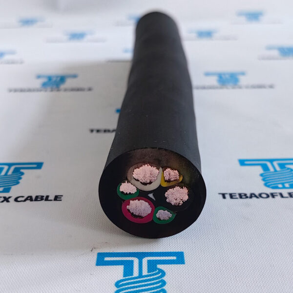
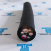
2000V Round Type G GC 3/C EPR CPE Rubber Cable for Mining Track Equipment
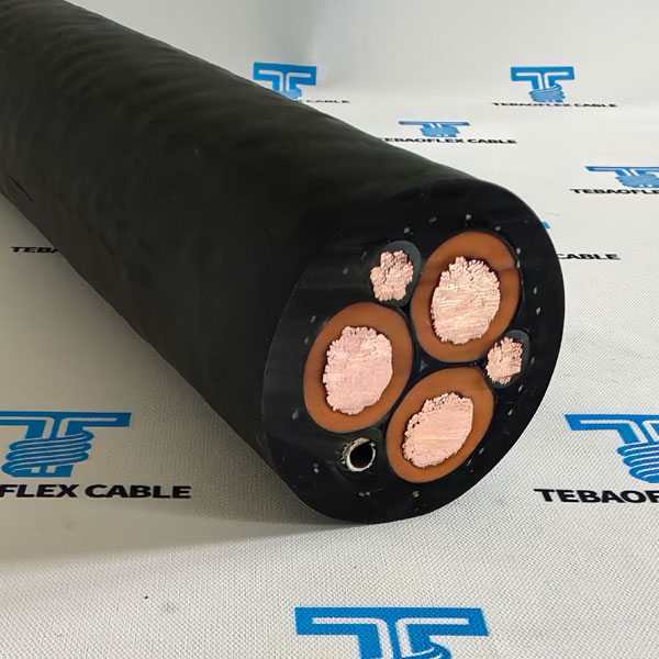
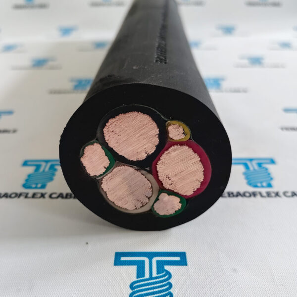
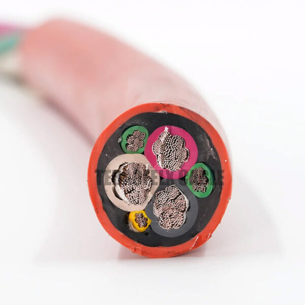
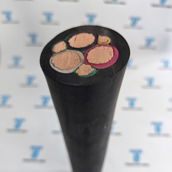
Type G-GC is a 2kv heavy‑duty portable trailing cable for underground coal mines,with 3 power cores + 2 ground conductors + 1 ground‑check conductor.
Type G GC Cable is specially suitable for use with mobile mining equipment such as continuous miners, drills, cutters, loading machines, and AC shuttle cars,.
The type G-GC is for applications where grounding conductors and a ground check conductor are required. Recommended maximum continuous conductor temperature is 90°C.
- Rated voltage2000V
- ConductorAnnealed tin coated rope stranded copper
- InsulationEthylene-propylene rubber (EPR)
- JacketExtra-heavy-duty black CPE
- Max. conductor temperature90°C
- Size range8 AWG – 500 kcmil
- Nominal outside diameter0.97 – 3.03 in.
- Approx. weight600 – 8900 lbs per 1,000 ft
1 SCOPE: This specification describes 3 conductor round type G-GC portable power cable with ethylene-propylene rubber insulation for use on circuits not exceeding 2000 volts at a maximum continuous conductor temperature of 90°c. These cables are intended for use on AC of track equipment such as continuous miners, shuttle cars, cuting machines, loading machines and drills, as well as conveyors and pumps.
For sizes, specifications and quotation enquiries, visit the TEBAOFLEX Type G-GC 2000V product page.
Specifications
Technical data
Technical Parameter of 2000V Round Type G-GC 3/C Mining Cable
| Size AWG | Power Conductors | Grounding Conductors | Nominal Outside Dimensions in. | Approx. Weight lbs. per 1,000 ft. | Ampacity3 | ||
|---|---|---|---|---|---|---|---|
| No. of Wires per Conductor | Insulation Thickness mils | Size AWG | No. of Wires per Conductor | 40°C Ambient Temp | |||
| 8 | 133 | 60 | 10 | 49 | 0.97 | 600 | 59 |
| 6 | 259 | 60 | 10 | 49 | 1.05 | 750 | 79 |
| 4 | 259 | 60 | 8 | 133 | 1.19 | 1070 | 104 |
| 2 | 259 | 60 | 7 | 133 | 1.34 | 1480 | 138 |
| 1 | 259 | 80 | 6 | 133 | 1.51 | 1890 | 161 |
| 1/0 | 266 | 80 | 5 | 133 | 1.65 | 2340 | 186 |
| 2/0 | 323 | 80 | 4 | 259 | 1.75 | 2750 | 215 |
| 3/0 | 418 | 80 | 2 | 259 | 1.89 | 3377 | 249 |
| 4/0 | 532 | 80 | 2 | 259 | 2.04 | 3980 | 287 |
| 250 | 627 | 95 | 2 | 259 | 2.39 | 5000 | 320 |
| 350 | 888 | 95 | 1/0 | 266 | 2.68 | 6750 | 394 |
| 500 | 1221 | 95 | 2/0 | 323 | 3.03 | 8900 | 487 |
1 Jacket – Black CPE is standard. Colored CPE jackets available upon request.
2 Ground Check Conductor
– 10 AWG (minimum 49 strand 7×7) ground check conductor on 8 AWG through 2 AWG cable.
-8 AWG (minimum 133 strand 7×19) ground check conductor on 1 AWG through 4/0 AWG cable.
-6 AWG (minimum 133 strand 7×19) ground check conductor on 250 kcmil and larger cable.
3 Ampacity – Based on continuous duty at 90°C conductor temperature.
4. Tolerances: -± .030″ 8-1 AWG
± .040″ 1/0 – 2/0 AWG
± .050″ 3/0 – 4/0 AWG
± .060″ 250 – 500 kcmil
Reel Correction Factors
For use with ampacities when one or more layers of type g gc mining cable are wound on a reel. Cables must be derated to prevent over heating on reel.
| Number of Layers | Multiplying Correction Factors |
|---|---|
| 1 | 0.85 |
| 2 | 0.64 |
| 3 | 0.45 |
| 3 | 0.35 |
Standards & References
Applicable standards
- 2. STANDARDS: ICEA S-75-381/NEMA WC-58, ASTM B-172, ICEA S-68-516/NEMA WC-8, ASTM B-33
Construction
Material and build-up
Three Conductor Round Type G-GC Mining Cable Specification:
- 3. CONDUCTORS: Annealed tin coated rope stranded conductors in accordance with ICEA and ASTM.
- 4. INSULATION: The insulation shall be ethylene-propylene rubber (EPR) extruded insulation.
The average thickness of the insulation wall over the conductor shall be as specified in Table 3-12 of ICEA S-75-381.
The minimum thickness of insulation shall not be less than 90% of the specified average value. - 5. CIRCUIT IDENTIFICATlON: Color coding of power conductors shall be black, white and red in accordance with Par. 7.2.15.1 of lCEA. Stock cables shall have colored insulation.
- 6. GROUNDING CONDUCTORS: The grounding conductors shall be annealed tin coated copper of not less than the size and number of wires in Table 3-12 of lCEA S-75-381 for the corresponding power conductor sizes. Each grounding conductor shall be covered with a green Mylar tape.
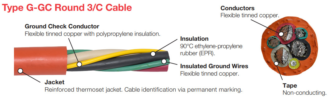
- 7. GROUND CHECK CONDUCTOR: The ground check conductor shall be as given in Table 3-12 of ICEA S-75-381 for the corresponding power conductor sizes. A minimum of 49 strands of annealed copper shall be used. The conductor shall have a yellow TPE insulation.
- 8. ASSEMBLY CORE: Sizes 4/0AWG and smaller: Three power conductors shall be cabled together with a left-hand lay meeting the requirements of Table 3-5 of IcEA S-75-381, the ground check conductor shall be laid in the valley between the black and white power conductors, a tinned copper grounding conductor in each of the other two valleys and a synthetic reinforcing binder overall. This assembly wil provide integral filing when the jacket is applied. Sizes 250 MCM and larger: Three power conductors shall be cabled together with a left-hand lay meeting the requirements of Table 3-5 of 1CEA S-75-381, the ground check conductor shall be laid in the valley between the black and white power conductors and a tinned copper grounding conductor in each of the other two valleys, with cured rubber fillers as required to make an essentially round core, synthetic binder and a single faced rubber filled binder tape applied overall.
- 9. JACKET: A CPE jacket shall be extruded over the assembly in accordance with Par. 3.21 of ICEA S-75-381, The standard jacket for al sizes is extra-heavy-duty black CPE or colors can be provided. All jackets meet the requirements of lCEA S-75-381 Table 3-3, and have a smooth dense surface that is highly resistant to cutting, abrasion, chemicals, sunlight and flame. it has excellent resistance to heat, moisture and the oils commonly used in mining applications.
- 10.OUTSIDE DIAMETER: Shall be in accordance with ICEA S-75-381 Table 3-12, and tolerances shall meet the requirements of ICEA S-75-381 Par 3.22.2.
- 11. SURFACE LEGEND: Shal lbe embossed in the jacket showing 600/2000v 3/c (size) Tvpe G-GC. Additional information can be furnished on the surface legend to special order.
- 12. TEARS: Cable shall be tested in accordance with applicable ICEA reguirements.
More Details
Comparison and references
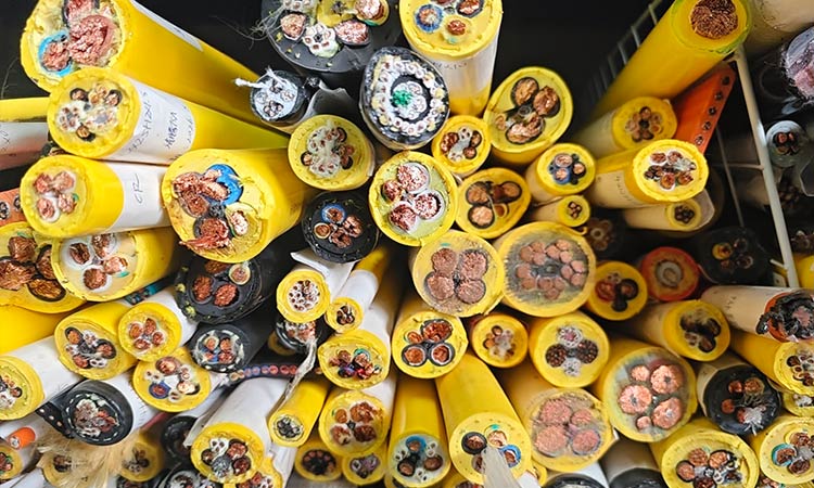
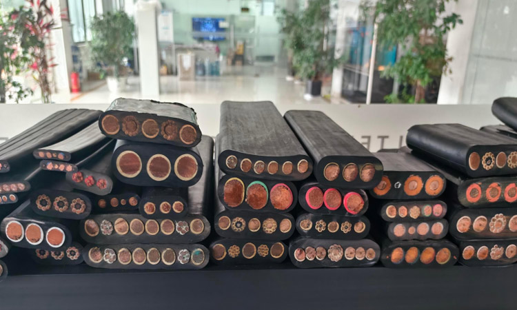
TEBAOFLEX CABLE Heavy-duty Mining Cable Product Process
TEBAOFLEX CABLE GROUP are equipped with world-class production facilities dedicated to manufacturing heavy-duty special rubber-sheathed cables, supported by a professional team of experienced cable technical engineers.
All our type g gc mining cable products are strictly manufactured and tested in full compliance with internationally recognized standards including ICEA and VDE. We adhere to rigorous quality control procedures throughout every production process to ensure reliable performance, excellent durability and stable quality of each cable.
TEBAOFLEX CABLE GROUP advanced manufacturing technology and standardized inspection systems enable our products to meet stringent global application requirements, delivering trustworthy solutions for various heavy-duty industrial and engineering scenarios worldwide.
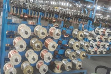
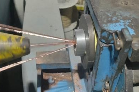
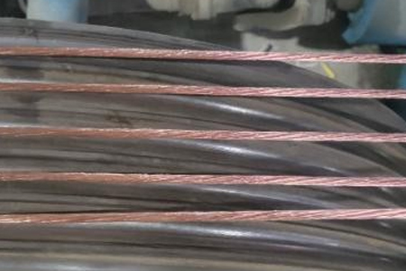
1. Conductor Preparation & Extrusion
Phase Conductors: Start with finely stranded, tinned, soft-annealed copper wire. Extrude a semi-conducting layer over the conductor to act as a conductor shield and ensure smooth electrical fields.
Primary Insulation: Extrude a layer of Ethylene Propylene Rubber (EPR) over the semi-conducting layer. An additional semi-conducting EPR layer is then extruded over the insulation as a strippable insulation shield.
Ground & Ground Check Conductors: Prepare uninsulated flexible tinned copper ground wires and a ground check wire. The ground check wire must be extruded with high-strength, colored polypropylene insulation (typically yellow)
2. Shielding & Core Assembly
Braid Shielding: Apply a composite tinned copper and color-coded textile/nylon braid (Black, Blue, Red for phase identification) over each of the insulated phase conductors to act as an individual electrostatic shield.
Cabling (Twisting): Lay up the three shielded phase conductors, two uninsulated ground conductors, and the yellow ground check conductor together with suitable rubber fillers to achieve a perfectly circular cross-section.
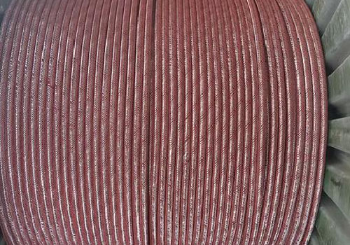
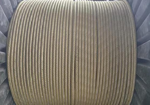
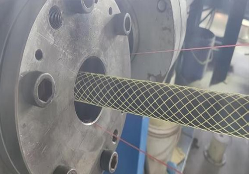
Bedding & Reinforcement: Wrap the cabled core with a single-faced rubber-filled binder tape and apply a reinforcing twine (reinforcing braid) to provide mechanical strength.
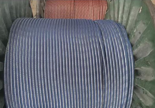
3. Jacketing(Inner Sheath and Ourter Sheath)
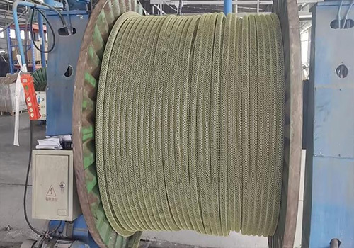
Inner & Outer Sheath: Extrude a heavy-duty thermosetting Chlorinated Polyethylene (CPE) compound over the assembly to form the inner jacket. For heavy-duty mining grades, apply a second outer CPE jacket.
Mold-Curing: For strict mining applications, the cable must pass through a continuous vulcanization (CV) or mold-curing process to cross-link the thermoset rubber and deliver extreme abrasion, oil, and chemical resistance.
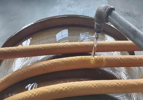
2kV Type G GC 3 /C Mining Cable Installation Steps
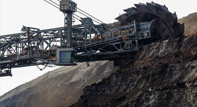
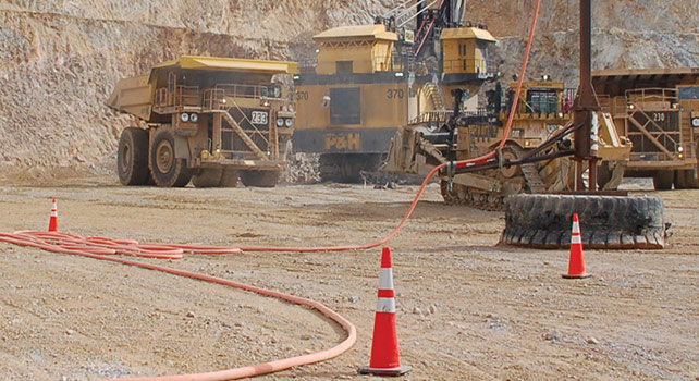
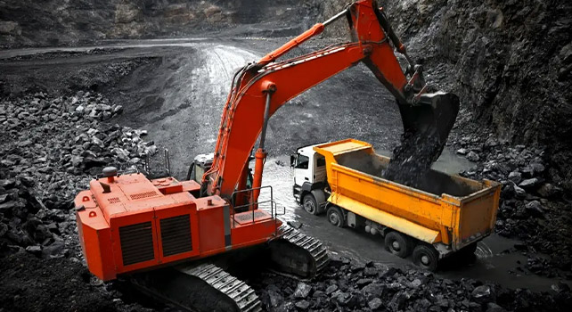
- 1. Safety Preparations
Confirm the Type G-GC cable voltage class (2000V). Wear PPE: insulated gloves, safety glasses, steel-toe boots. - 2. Cable Inspection & Route Planning
Plan route: avoid sharp edges, high heat, and excessive bending. Minimum bending radius: 6× OD; no kinks or sharp bends. - 3. Connector Installation (Camlock / Mine-style)
Slide backshell, gasket, and strain relief onto cable. Wrap copper shim around bare conductors for proper seating. Insert into camlock body, tighten set screws evenly.
Secure strain relief (critical for mining drag/pull).
Seal jacket entry to prevent moisture/dirt ingress. - 4. Cable Laying & Securing
Lay cable in straight runs; use rollers to avoid dragging on sharp surfaces.
Request this cable.
Send the core configuration, length and application details.
Quality Assurance
Testing at every stage in our own workshop and laboratory, from incoming copper to the packed drum.
Raw Material Inspection
Every batch of copper rod, rubber compound and reinforcing material is checked before it reaches the line.
- Copper: conductor resistance, elongation and surface condition on incoming rod and drawn wire
- EPR, CPE, PUR and silicone compounds: hardness, tensile strength, elongation and ageing samples from each mix
- Suppliers and batch numbers are recorded so every drum can be traced back to its materials
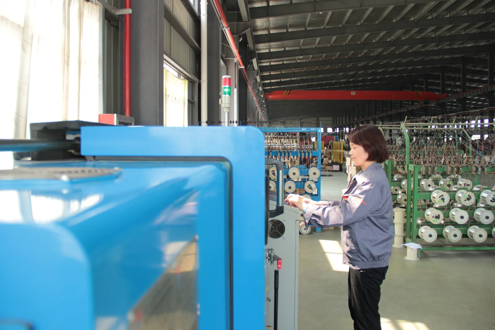
Manufacturing Process Control
Stranding, insulation extrusion, core assembly and sheathing run under recorded process parameters.
- Class 5/6 stranding with lay length and tension monitored for trailing and reeling flexibility
- Continuous-vulcanisation extrusion with wall thickness and spark tests logged on every length
- Operators sign off each stage before the cable moves to the next machine
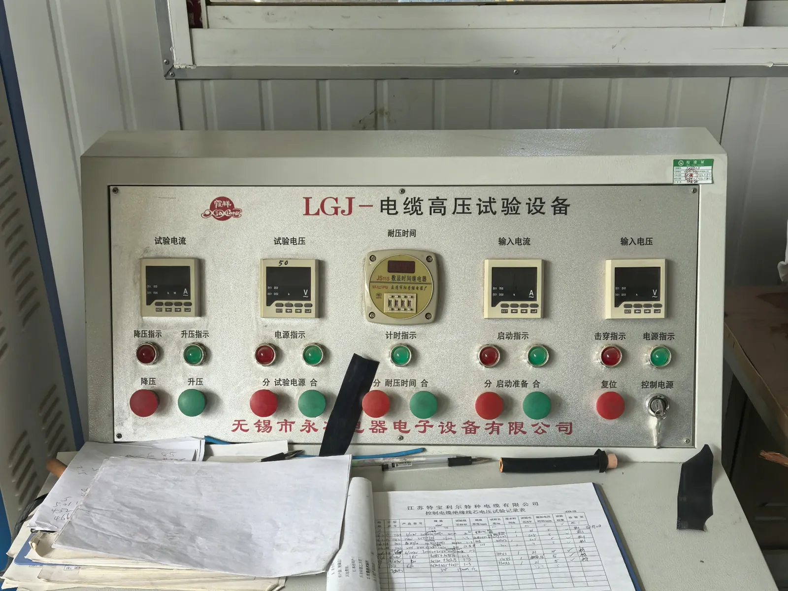
Electrical Testing
Finished lengths go through the routine tests required by the referenced VDE, ICEA, IEC or NEK standard.
- Conductor resistance and insulation resistance on every length
- Voltage withstand (3.5 kV and higher) and partial-discharge measurement in the shielded HV laboratory
- Screen and pilot-core continuity checks for mining and reeling constructions
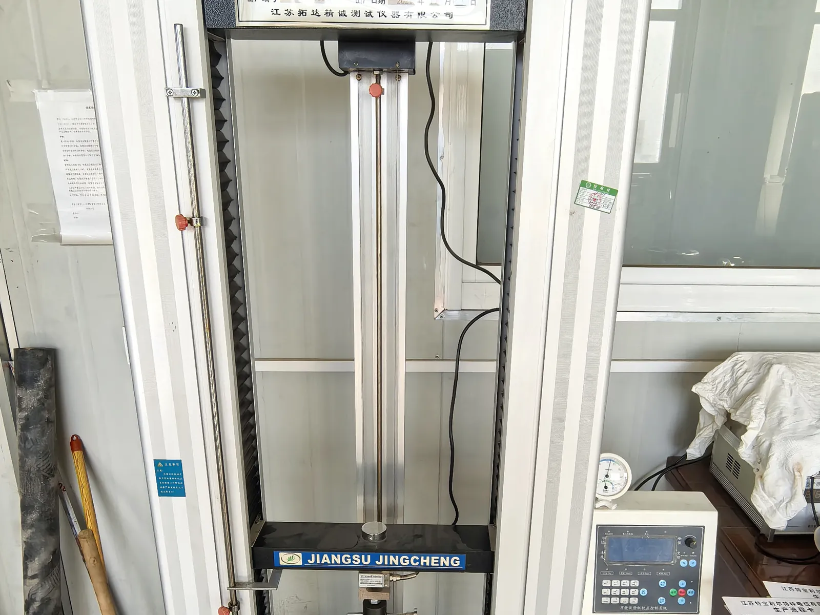
Mechanical and Ageing Tests
Samples from production are tested for the duty a mining, crane or submersible cable will actually see.
- Tensile strength and elongation of insulation and sheath before and after ageing
- Hot-set, ozone, oil-immersion and low-temperature bending tests
- Constant-temperature water bath for insulation resistance of submersible constructions
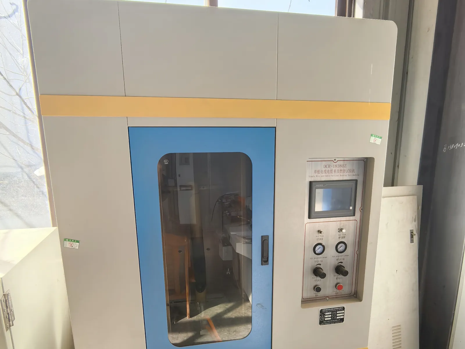
Flame Test and Final Inspection
Before packing, the cable is checked against the order and the flame-performance requirement of its standard.
- Single-cable vertical flame test to IEC 60332-1-2 where specified
- Metre marking, printing, drum length and appearance inspection
- Test report and packing list issued with every shipment
Related products
-
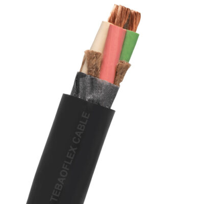
ICEA 2000V Flat&Round Type W Portable Power Mining Cable 4 0 AWG
-
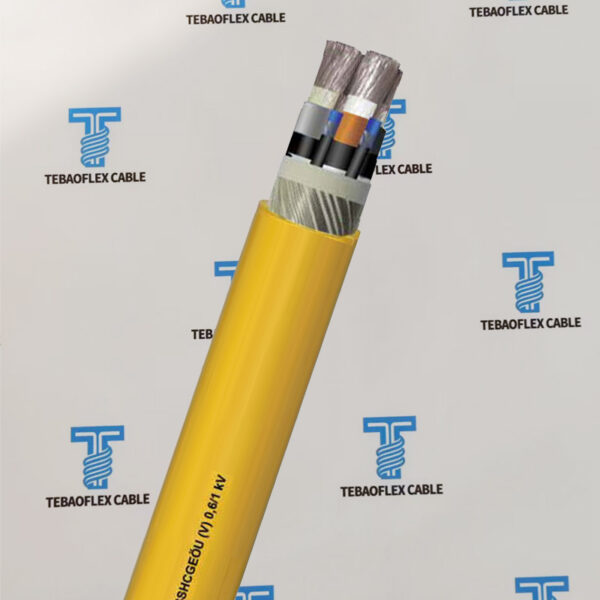
0.6/1kV NSSHCGEÖU(V) Mining Cable 3×70, 3×95, 3×120, 3×150
-
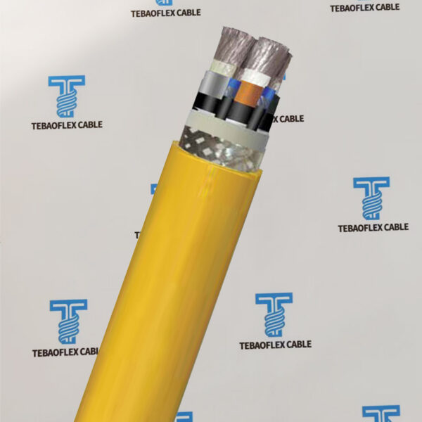
Heavy-Duty NSSHCGEÖU(Z) Reinforced Version Mining Cable
-
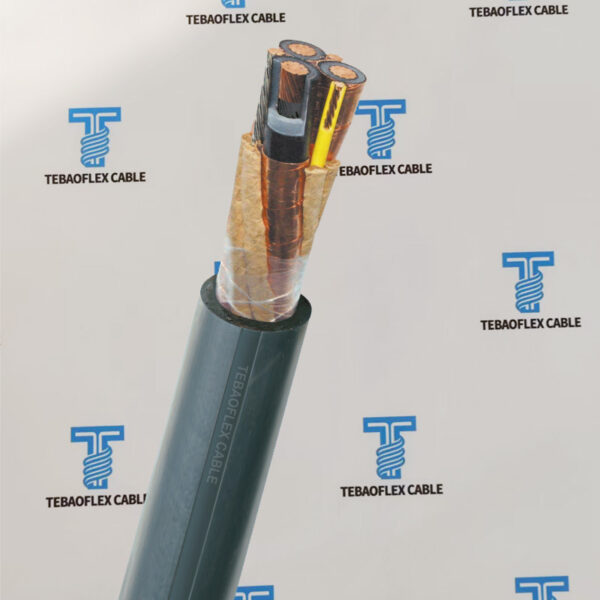
5kV 8kV 15kV Type MP-GC 3/C XLPE/PVC or EPR/CPE Mining Power Feeder Cable
-
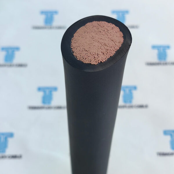
DAA1093 AAR S-501 / RP-585 125°C XLPO DLO Diesel Locomotive Wire 600V/2000V
-
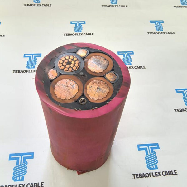
MV Motor RTS (N)TSCGEWTOEUS OFE Reeling Cable 3×70 + 3×35/3 + (20×2.5)C + 24FO (9/125)
-
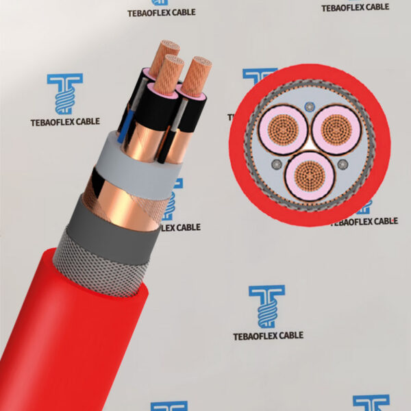
(N)3GHSSHCH LSZH Tunnelling & Underground Mining Cable
-
NTMCGCWOEU / (N)TMCGCWOEU 6-30kV Single-Core EPR Heavy-Duty Rubber Cable
Need Pricing for This Cable?
Tell us the length, cores, cross-section and delivery country and we will reply with a quotation and datasheet.