
NTMCGCWOEU / (N)TMCGCWOEU 6-30kV Single-Core EPR Heavy-Duty Rubber Cable
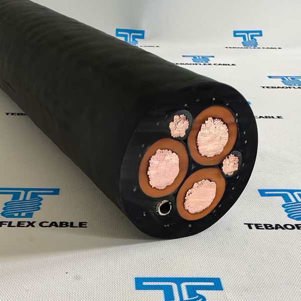
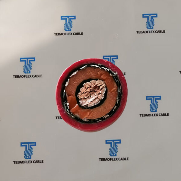
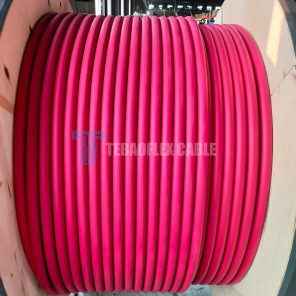
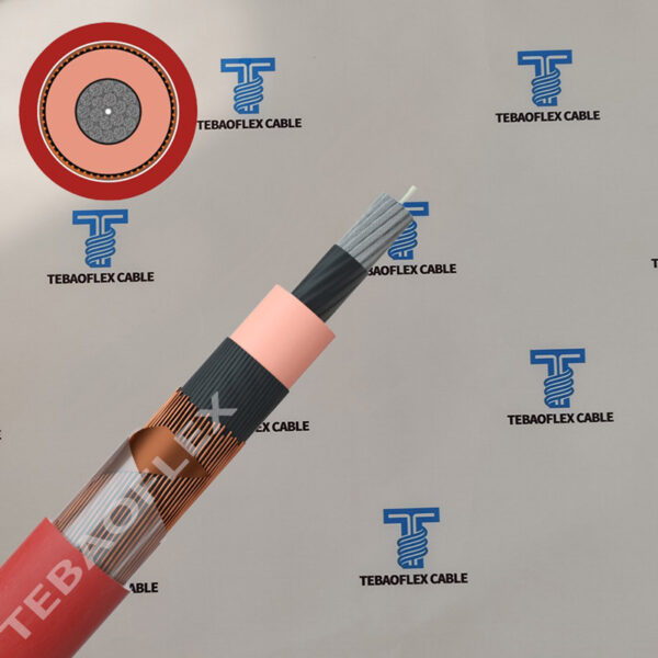
NTMCGCWOEU and (N)TMCGCWOEU are single-core flexible EPR rubber cables for medium-voltage connections of mobile transformer substations, mining equipment and heavy mobile machinery, with tinned class 5 copper, a tinned copper wire screen and a red 5GM5 rubber sheath.
- Voltage range Uo/U3.6/6 kV to 20/35 kV
- ConductorTinned Cu, IEC 60228 class 5
- InsulationEPR (ethylene propylene rubber)
- ScreenTinned Cu wires, 16 or 25 mm²
- Outer sheath5GM5 rubber, red
- Conductor temperature90 °C; 250 °C short circuit
- Ambient, flexible use-25 °C to +60 °C
- Sizes1×25/16 to 1×400/35 mm²
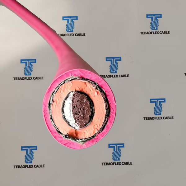
NTMCGCWOEU is a single-core flexible medium-voltage cable with finely stranded tinned copper, EPR insulation between semi-conductive layers, a tinned copper wire screen and a durable red rubber sheath. It resists oil, weather and electromagnetic interference and works reliably in static service or with occasional movement. In (N)TMCGCWOEU the bracketed (N) marks a design based on the DIN VDE 0250-813 type.
The cable is used for short connections of mobile transformer substations to overhead lines, for mining equipment and heavy mobile machinery, and for outdoor facilities. Dimension tables cover the 3.6/6 kV, 6/10 kV, 8.7/15 kV and 12/20 kV classes from 1×25/16 to 1×400/35, and the rated voltage table runs up to 20/35 kV.
Browse the VDE mining cable category for related cables.
Application & Features
Selection overview
A mobile transformer substation moves from one site to the next and has to be connected to the overhead line or the site network each time. The connection is short, it is made and broken repeatedly, and it is exposed to rain, sun, frost and mechanical knocks. A single-core flexible rubber cable suits this duty: each phase is light enough to handle, the class 5 conductor bends into the terminal box, and the 5GM5 sheath stands up to outdoor use. The same cable connects transformers, switchgear and drives on mining equipment and heavy mobile machinery.
The temperature limits separate the two kinds of duty: -40 °C to +80 °C ambient in fixed installation, but -25 °C to +60 °C when the cable is used fully flexible. For each size the tables give the minimum bending radius for fixed laying (about 6 times the outer diameter) and for free movement (about 10 times), the maximum tensile load, the current-carrying capacity, the capacitance and the short-circuit current, so cross-section and voltage class can be chosen together.
- Mobile transformer substationsShort connections of mobile transformer substations to overhead lines and site networks.
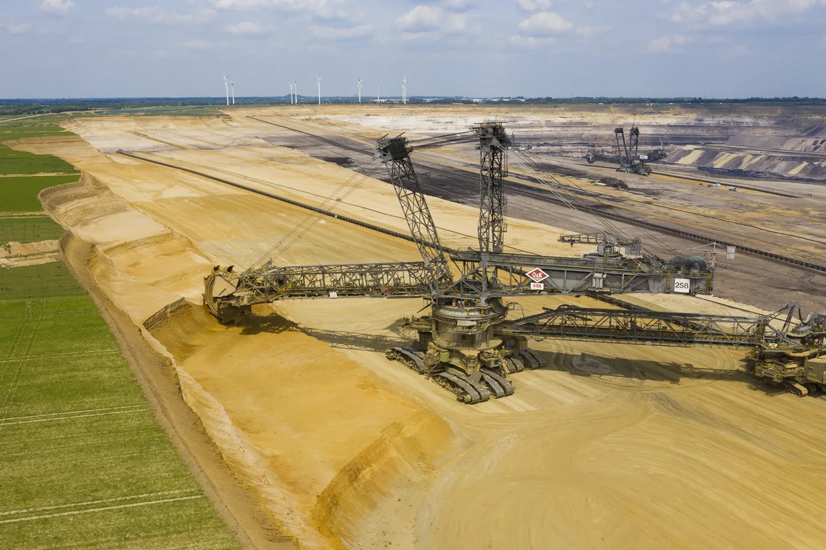
- Mining equipmentMedium-voltage connections on mining equipment and heavy mobile machinery that is moved often.
- Outdoor facilitiesUnrestricted indoor and outdoor use with ozone, UV and moisture resistance.
- Four tabulated voltage classesFull data for 3.6/6, 6/10, 8.7/15 and 12/20 kV from 1×25/16 to 1×400/35.
Specifications
Technical data
Typical NTMCGCWOEU values for the 3.6/6 kV to 12/20 kV classes. The final construction is confirmed on the TEBAOFLEX datasheet issued with your quotation.
Construction, thermal and chemical data
| Parameter | Value |
|---|---|
| Conductor | Tinned annealed copper wires to VDE 0295 or IEC 60228 class 5 |
| Insulation | Ethylene propylene rubber (EPR) |
| Screen | Spinning of tinned copper wires, cross-section 16 or 25 mm² (35 mm² on 1×400/35) |
| Outer sheath | Rubber compound 5GM5, red |
| Max. operating temperature of the conductor | 90 °C |
| Max. short circuit temperature of the conductor | 250 °C |
| Ambient temperature, fixed installation | Min. -40 °C; max. +80 °C |
| Ambient temperature, fully flexible operation | Min. -25 °C; max. +60 °C |
| Performance against fire | IEC 60332-1-2 |
| Resistance to oil | IEC 60811-404 |
| Weather resistance | Unrestricted use outdoors and indoors, resistant to ozone, UV and moisture |
Rated voltages of (N)TMCGCWOEU cable
| Rated voltage Uo/U | Max. permissible operating voltage AC | Max. permissible operating voltage DC |
|---|---|---|
| 3.6/6 kV | 4.2/7.2 kV | 5.4/10.8 kV |
| 6/10 kV | 6.9/12 kV | 9/18 kV |
| 8.7/15 kV | 10.4/18 kV | 13.5/27 kV |
| 12/20 kV | 13.9/24 kV | 18/36 kV |
| 14/25 kV | 17.3/30 kV | 22.5/45 kV |
| 18/30 kV | 20.8/36 kV | 27/54 kV |
| 20/35 kV | 24.2/42 kV | 31.5/63 kV |
NTMCGCWOEU 3.6/6 kV: dimensions and electrical data
| Cores × cross-section | Conductor diameter max. (mm) | Diameter over insulation nom. (mm) | Outer diameter min. (mm) | Outer diameter max. (mm) | Bending radius fixed min. (mm) | Bending radius free moving min. (mm) | Weight (kg/km) | Max. tensile load (N) | Conductor resistance (Ω/km) | Nominal operating capacitance (μF/km) | Current-carrying capacity (A) | Short-circuit current, conductor (kA) |
|---|---|---|---|---|---|---|---|---|---|---|---|---|
| 1×25/16KON | 6.4 | 14 | 20.6 | 22.1 | 133 | 221 | 820 | 375 | 0.795 | 0.26 | 178 | 3.58 |
| 1×35/16KON | 7.5 | 15.1 | 21.5 | 23 | 138 | 230 | 930 | 525 | 0.565 | 0.29 | 220 | 5.01 |
| 1×50/16KON | 9 | 16.6 | 23 | 24.5 | 147 | 245 | 1110 | 750 | 0.393 | 0.33 | 275 | 7.15 |
| 1×70/16KON | 10.8 | 18.4 | 25.1 | 27.4 | 164 | 274 | 1380 | 1050 | 0.277 | 0.38 | 340 | 10.01 |
| 1×95/16KON | 12.6 | 20.2 | 26.9 | 29.2 | 175 | 292 | 1630 | 1425 | 0.21 | 0.42 | 409 | 13.59 |
| 1×120/16KON | 14.2 | 21.8 | 28.5 | 30.8 | 185 | 308 | 1940 | 1800 | 0.164 | 0.46 | 479 | 17.16 |
| 1×150/25KON | 15.8 | 23.4 | 31.4 | 33.6 | 202 | 336 | 2410 | 2250 | 0.132 | 0.5 | 549 | 21.45 |
| 1×185/25KON | 17.4 | 25 | 33 | 35.2 | 211 | 352 | 2750 | 2775 | 0.108 | 0.54 | 627 | 26.46 |
| 1×240/25KON | 20.4 | 28.3 | 37.3 | 39.5 | 237 | 395 | 3430 | 3600 | 0.0817 | 0.6 | 734 | 34.32 |
| 1×300/25KON | 22.9 | 30.5 | 39.5 | 41.7 | 250 | 417 | 4000 | 4500 | 0.0641 | 0.68 | 843 | 42.9 |
NTMCGCWOEU 6/10 kV: dimensions and electrical data
| Cores × cross-section | Conductor diameter max. (mm) | Diameter over insulation nom. (mm) | Outer diameter min. (mm) | Outer diameter max. (mm) | Bending radius fixed min. (mm) | Bending radius free moving min. (mm) | Weight (kg/km) | Max. tensile load (N) | Conductor resistance (Ω/km) | Nominal operating capacitance (μF/km) | Current-carrying capacity (A) | Short-circuit current, conductor (kA) |
|---|---|---|---|---|---|---|---|---|---|---|---|---|
| 1×25/16KON | 6.4 | 14.8 | 19 | 20.5 | 123 | 205 | 890 | 375 | 0.795 | 0.24 | 178 | 3.58 |
| 1×35/16KON | 7.5 | 15.9 | 22.3 | 23.8 | 143 | 238 | 1000 | 525 | 0.565 | 0.27 | 220 | 5.01 |
| 1×50/16KON | 9 | 17.4 | 23.8 | 25.3 | 152 | 253 | 1190 | 750 | 0.393 | 0.3 | 275 | 7.15 |
| 1×70/16KON | 10.8 | 19.2 | 25.9 | 28.2 | 169 | 282 | 1460 | 1050 | 0.277 | 0.34 | 340 | 10.01 |
| 1×95/16KON | 12.6 | 21 | 27.7 | 30 | 180 | 300 | 1710 | 1425 | 0.21 | 0.38 | 409 | 13.59 |
| 1×120/16KON | 14.2 | 22.6 | 30.3 | 32.6 | 196 | 326 | 2070 | 1800 | 0.164 | 0.42 | 479 | 17.16 |
| 1×150/25KON | 15.8 | 24.2 | 32.2 | 34.4 | 206 | 344 | 2470 | 2250 | 0.132 | 0.46 | 549 | 21.45 |
| 1×185/25KON | 17.4 | 25.8 | 33.8 | 36 | 216 | 360 | 2810 | 2775 | 0.108 | 0.49 | 627 | 26.46 |
| 1×240/25KON | 20.4 | 29.1 | 38.1 | 40.3 | 242 | 403 | 3490 | 3600 | 0.0817 | 0.54 | 734 | 34.32 |
| 1×300/25KON | 22.9 | 31.6 | 40.3 | 42.5 | 255 | 425 | 4150 | 4500 | 0.0641 | 0.59 | 843 | 42.9 |
| 1×400/25KON | 26.2 | 33 | 43 | 46 | 276 | 460 | 5000 | 6000 | 0.05 | 0.66 | 1024 | 57.2 |
NTMCGCWOEU 8.7/15 kV: dimensions and electrical data
| Cores × cross-section | Conductor diameter max. (mm) | Diameter over insulation nom. (mm) | Outer diameter min. (mm) | Outer diameter max. (mm) | Bending radius fixed min. (mm) | Bending radius free moving min. (mm) | Weight (kg/km) | Max. tensile load (N) | Conductor resistance (Ω/km) | Nominal operating capacitance (μF/km) | Current-carrying capacity (A) | Short-circuit current, conductor (kA) |
|---|---|---|---|---|---|---|---|---|---|---|---|---|
| 1×25/16KON | 6.4 | 17 | 23.4 | 24.9 | 149 | 249 | 950 | 375 | 0.795 | 0.2 | 189 | 3.58 |
| 1×35/16KON | 7.5 | 18.1 | 24.9 | 27.1 | 163 | 271 | 1110 | 525 | 0.565 | 0.22 | 234 | 5.01 |
| 1×50/16KON | 9 | 19.6 | 26.4 | 28.6 | 172 | 286 | 1300 | 750 | 0.393 | 0.25 | 292 | 7.15 |
| 1×70/16KON | 10.8 | 21.4 | 28.1 | 30.4 | 182 | 304 | 1550 | 1050 | 0.277 | 0.28 | 360 | 10.01 |
| 1×95/16KON | 12.6 | 23.2 | 30.9 | 33.2 | 199 | 332 | 1880 | 1425 | 0.21 | 0.31 | 434 | 13.59 |
| 1×120/16KON | 14.2 | 24.8 | 32.5 | 34.8 | 209 | 348 | 2200 | 1800 | 0.164 | 0.34 | 505 | 17.16 |
| 1×150/25KON | 15.8 | 26.4 | 34.4 | 36.6 | 220 | 366 | 2610 | 2250 | 0.132 | 0.37 | 582 | 21.45 |
| 1×185/25KON | 17.4 | 28 | 37 | 39.2 | 235 | 392 | 3090 | 2775 | 0.108 | 0.4 | 664 | 26.46 |
| 1×240/25KON | 20.4 | 31 | 40 | 42.2 | 253 | 422 | 3680 | 3600 | 0.0817 | 0.45 | 781 | 34.32 |
| 1×300/25KON | 22.9 | 33.5 | 42.2 | 44.4 | 266 | 444 | 4290 | 4500 | 0.0654 | 0.49 | 898 | 42.9 |
| 1×400/35KON | 26.2 | 36.8 | 45.2 | 48.2 | 289 | 482 | 5290 | 6000 | 0.0495 | 0.55 | 1074 | 57.2 |
NTMCGCWOEU 12/20 kV: dimensions and electrical data
| Cores × cross-section | Conductor diameter max. (mm) | Diameter over insulation nom. (mm) | Outer diameter min. (mm) | Outer diameter max. (mm) | Bending radius fixed min. (mm) | Bending radius free moving min. (mm) | Weight (kg/km) | Max. tensile load (N) | Conductor resistance (Ω/km) | Nominal operating capacitance (μF/km) | Current-carrying capacity (A) | Short-circuit current, conductor (kA) |
|---|---|---|---|---|---|---|---|---|---|---|---|---|
| 1×25/16KON | 6.4 | 19 | 25.7 | 28 | 168 | 280 | 1150 | 375 | 0.795 | 0.18 | 189 | 3.58 |
| 1×35/16KON | 7.5 | 20.1 | 26.8 | 29.1 | 175 | 291 | 1290 | 525 | 0.565 | 0.19 | 234 | 5.01 |
| 1×50/16KON | 9 | 21.6 | 28.3 | 30.6 | 184 | 306 | 1490 | 750 | 0.393 | 0.22 | 292 | 7.15 |
| 1×70/16KON | 10.8 | 23.4 | 31.1 | 33.4 | 200 | 334 | 1750 | 1050 | 0.277 | 0.24 | 360 | 10.01 |
| 1×95/16KON | 12.6 | 25.2 | 32.9 | 35.2 | 211 | 352 | 2110 | 1425 | 0.21 | 0.27 | 434 | 13.59 |
| 1×120/16KON | 14.2 | 26.8 | 34.5 | 36.8 | 221 | 368 | 2400 | 1800 | 0.164 | 0.29 | 505 | 17.16 |
| 1×150/25KON | 15.8 | 28.4 | 37.4 | 39.6 | 238 | 396 | 2910 | 2250 | 0.132 | 0.32 | 582 | 21.45 |
| 1×185/25KON | 17.4 | 30 | 39 | 41.2 | 247 | 412 | 3270 | 2775 | 0.108 | 0.34 | 664 | 26.46 |
| 1×240/25KON | 20.4 | 33 | 42 | 44.2 | 265 | 442 | 3880 | 3600 | 0.0817 | 0.39 | 781 | 34.32 |
| 1×300/25KON | 22.9 | 34.7 | 44 | 47 | 282 | 470 | 4540 | 4500 | 0.0654 | 0.43 | 898 | 42.9 |
| 1×400/35KON | 26.2 | 39.3 | 49.4 | 52.4 | 314 | 524 | 5760 | 6000 | 0.0495 | 0.5 | 1074 | 57.2 |
Selection note: current-carrying capacity depends on the laying and operating conditions, and the short-circuit current depends on the fault duration. Before ordering, ask our engineers to confirm the current rating for your installation, the short-circuit duration behind the kA values, and whether the sheath marking must read NTMCGCWOEU or (N)TMCGCWOEU.
Standards & References
Applicable standards and compliance
- Construction and useDIN VDE 0250-813 (construction), DIN VDE 0250-1 (general requirements) and DIN VDE 0298-3 (guide to use).
- Electrical and non-electrical testsElectrical tests to DIN VDE 0472-501, 503, 508; non-electrical tests to DIN VDE 0472-401, 402,602, 303, 615.
- Fire performanceTests under fire conditions to DIN VDE 0472-803, 804; flame retardant to VDE 0482-332-1-2, DIN EN 60332-1-2 and IEC 60332-1.
- Oil and weather resistanceOil resistant to HD/EN/IEC 60811-2-1 and DIN VDE 0473-811-2-1 (IEC 60811-404); unrestricted use outdoors and indoors, resistant to ozone, UV and moisture.
- ApprovalsMine approvals, test reports and marking requirements are confirmed and quoted per order.
Construction
Material and build-up
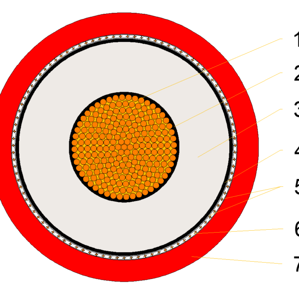
NTMCGCWOEU is a round single-core cable with seven layers from the conductor outward. Semi-conductive layers on both sides of the EPR insulation control the electric field, and the concentric copper wire screen carries charging and fault current; its cross-section is the second figure in the size code, for example 16 mm² in 1×95/16.
- Conductor: Tinned annealed copper wires to VDE 0295 or IEC 60228 class 5, from 6.4 mm maximum diameter on 25 mm² to 26.2 mm on 400 mm².
- Inner semi-conductive layer: Semi-conductive tape plus a thermosetting compound over the conductor.
- Insulation: Ethylene propylene rubber (EPR); the diameter over insulation grows with the voltage class, for 1×95/16 from 20.2 mm at 3.6/6 kV to 25.2 mm at 12/20 kV.
- Outer semi-conductive layer: Thermosetting semi-conductive compound over the insulation.
- Semi-conductive tape: Tape over the outer semi-conductive layer, under the screen.
- Screen: Spinning of tinned copper wires with a cross-section of 16 or 25 mm², and 35 mm² on 1×400/35.
- Outer sheath: Rubber compound 5GM5, red. Special versions on request, for example a halogen-free version with a 5GM3 outer sheath.
FAQ
Selection questions
What is the difference between NTMCGCWOEU and (N)TMCGCWOEU?
Both are single-core flexible EPR rubber cables with the same core materials, electrical parameters and environmental resistance. NTMCGCWOEU without brackets refers to the type defined in DIN VDE 0250-813; the bracketed (N) marks a design based on that type. NTMCGCWOEU is the usual choice for heavy-duty mobile machinery, mining equipment and outdoor facilities with frequent movement, while (N)TMCGCWOEU serves standard industrial wiring, stationary equipment and light mobile devices. For a version aimed at frequent movement and high mechanical stress, see (SI) NTMCGCWOEUS.
What does 1×95/16KON mean?
One core with a 95 mm² phase conductor and a 16 mm² concentric screen of tinned copper wires; KON refers to that concentric screen. Sizes up to 120 mm² carry a 16 mm² screen and larger sizes a 25 mm² screen, except 1×400/35 at 8.7/15 kV and 12/20 kV, which has a 35 mm² screen.
Which voltage class do I need?
Choose the rated voltage Uo/U of your system: 3.6/6, 6/10, 8.7/15 or 12/20 kV in the dimension tables, and up to 20/35 kV in the rated voltage table. Each class also has a maximum permissible operating voltage, for example 6.9/12 kV AC and 9/18 kV DC for the 6/10 kV class. Higher classes have thicker insulation, so diameter, weight and bending radius grow with the voltage.
How tightly can the cable be bent?
The tables list the minimum bending radius per size: about 6 times the outer diameter for fixed laying and about 10 times for free movement. For 1×95/16 at 6/10 kV that is 180 mm fixed and 300 mm moving. In fully flexible operation keep to the ambient limits of -25 °C to +60 °C.
What should I send for a quotation?
Send the voltage class, cross-section and screen (for example 1×95/16 at 6/10 kV), the length of each connection, NTMCGCWOEU or (N)TMCGCWOEU marking, the type of duty (fixed, occasional movement or fully flexible), any halogen-free requirement and the approval your site needs. More flexible mining cables are in the VDE mining cable category.
Request this cable.
Send the voltage class, cross-section, connection lengths, the designation for the marking, the type of duty and any approval requirement.
Quality Assurance
Testing at every stage in our own workshop and laboratory, from incoming copper to the packed drum.
Raw Material Inspection
Every batch of copper rod, rubber compound and reinforcing material is checked before it reaches the line.
- Copper: conductor resistance, elongation and surface condition on incoming rod and drawn wire
- EPR, CPE, PUR and silicone compounds: hardness, tensile strength, elongation and ageing samples from each mix
- Suppliers and batch numbers are recorded so every drum can be traced back to its materials
Manufacturing Process Control
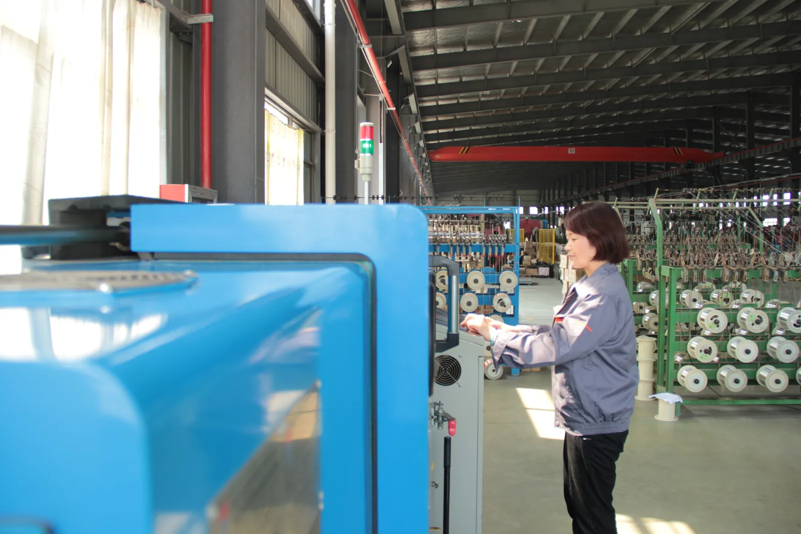
Stranding, insulation extrusion, core assembly and sheathing run under recorded process parameters.
- Class 5/6 stranding with lay length and tension monitored for trailing and reeling flexibility
- Continuous-vulcanisation extrusion with wall thickness and spark tests logged on every length
- Operators sign off each stage before the cable moves to the next machine
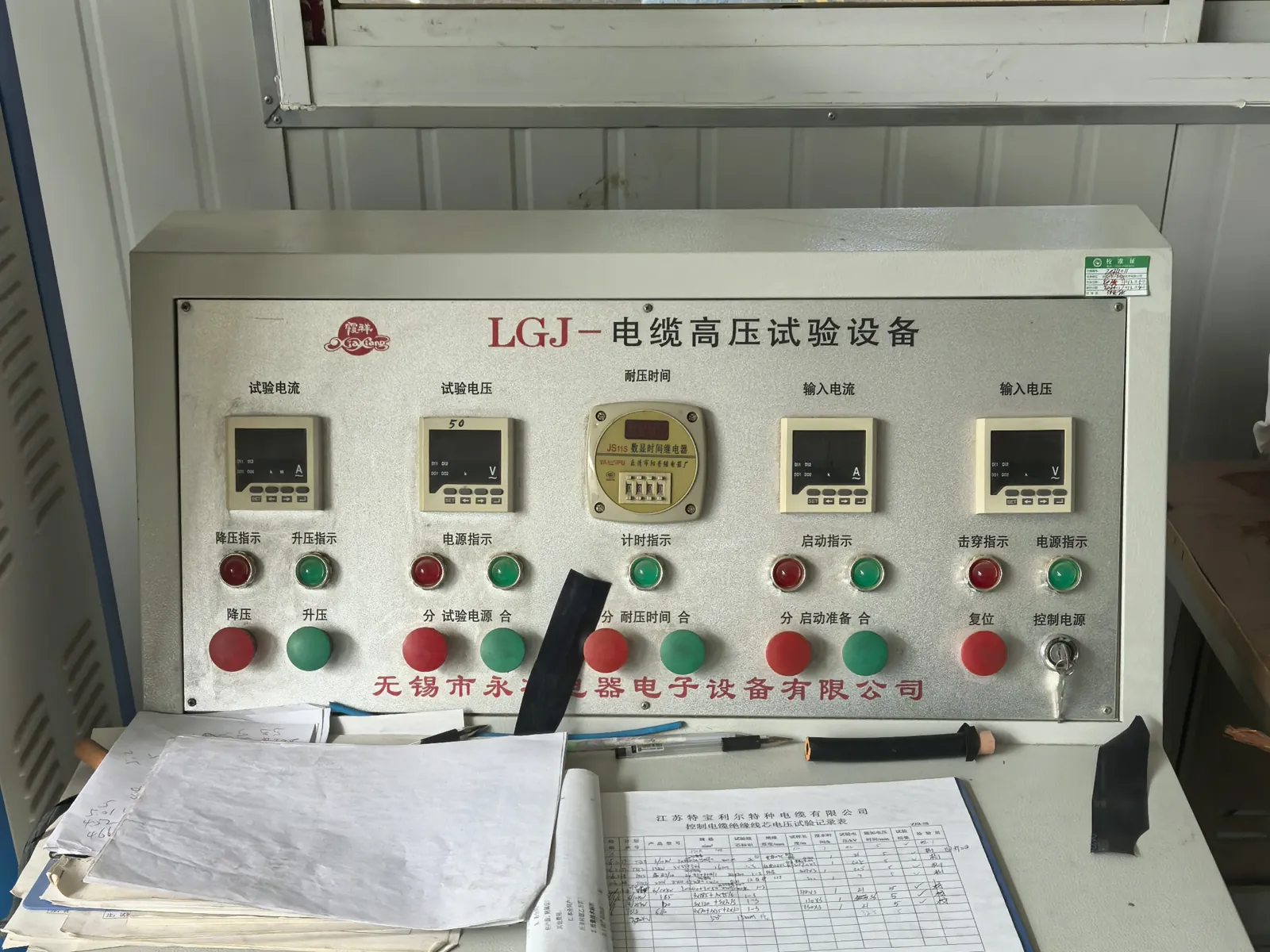
Electrical Testing
Finished lengths go through the routine tests required by the referenced VDE, ICEA, IEC or NEK standard.
- Conductor resistance and insulation resistance on every length
- Voltage withstand (3.5 kV and higher) and partial-discharge measurement in the shielded HV laboratory
- Screen and pilot-core continuity checks for mining and reeling constructions
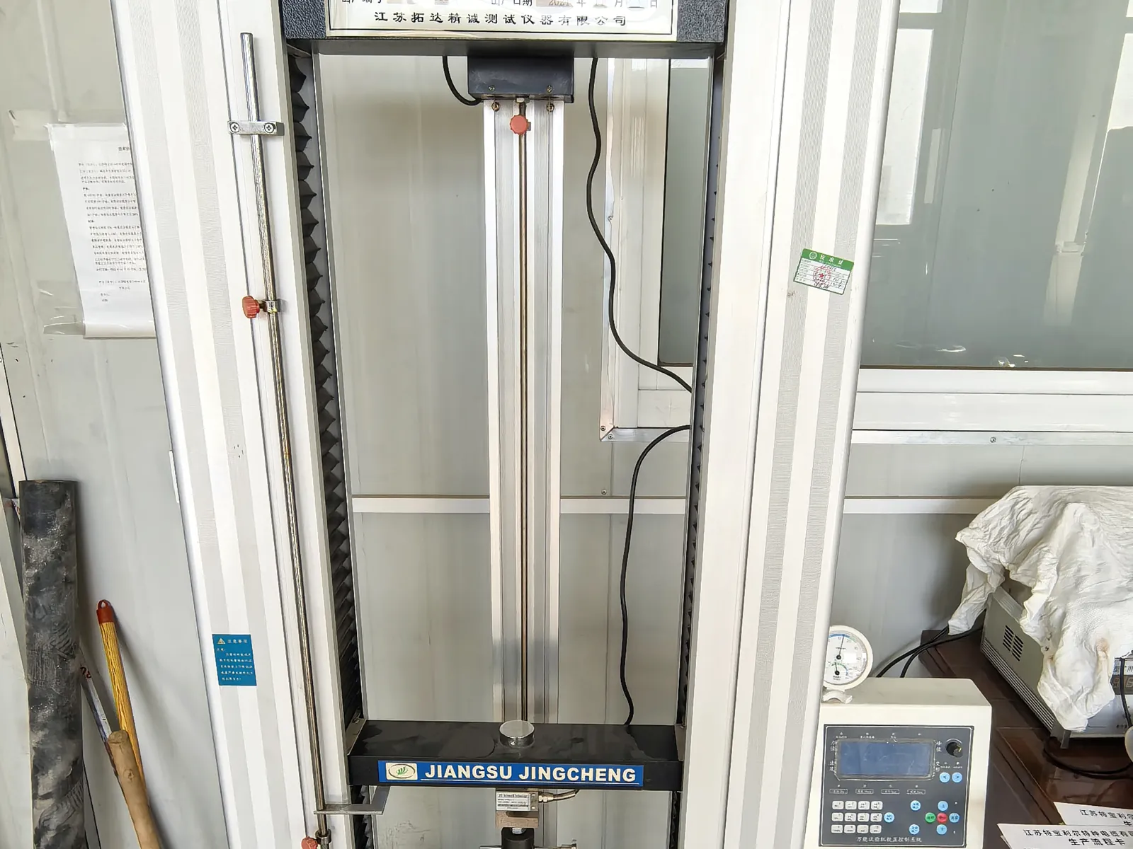
Mechanical and Ageing Tests
Samples from production are tested for the duty a mining, crane or submersible cable will actually see.
- Tensile strength and elongation of insulation and sheath before and after ageing
- Hot-set, ozone, oil-immersion and low-temperature bending tests
- Constant-temperature water bath for insulation resistance of submersible constructions
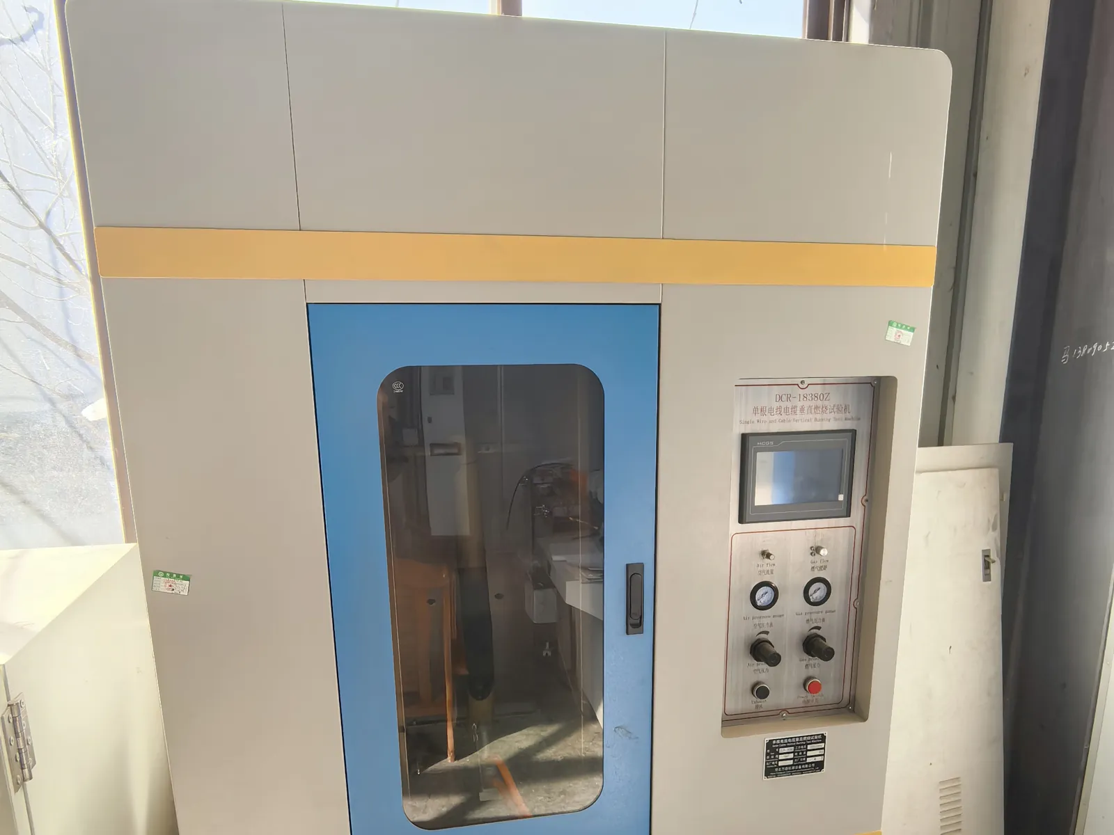
Flame Test and Final Inspection
Before packing, the cable is checked against the order and the flame-performance requirement of its standard.
- Single-cable vertical flame test to IEC 60332-1-2 where specified
- Metre marking, printing, drum length and appearance inspection
- Test report and packing list issued with every shipment
Related products
-
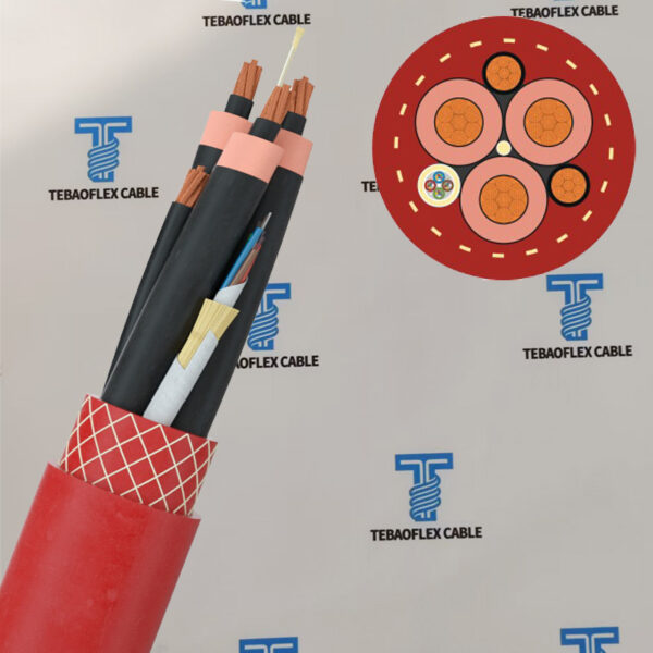
(N)TSCGEWÖU Submersible ABT FO(LWL) Mining Trailing Cable
-
Olflex SMK NSHTOU J Rubber Crane Reeling Cable
-
(N)3GHSSYCY Cable for Tunnel and Underground Mining
-
(N)3GHSSHCH LSZH Tunnelling & Underground Mining Cable
-
(N)TMCGCW11Y Cable | Medium Voltage Flexible Reeling Cable
-
Open-Cast Mining NTSCGEWOEU W 3E Cable in Water & Trailing
-

1kV NSHTOEU Scoops LHDs Underground Mining Reeling Cable
-
2000V 4 0 535 DLO Diesel Locomotive Cable 90°C EPR-CPE RHH RHW-2 for Mining
Need Pricing for This Cable?
Tell us the length, cores, cross-section and delivery country and we will reply with a quotation and datasheet.