
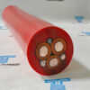
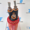
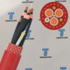
6kV-35kV R-(N)TSCGEWOEU FO LWL Reeling Mines Cable
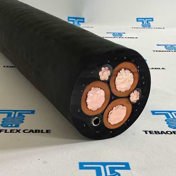
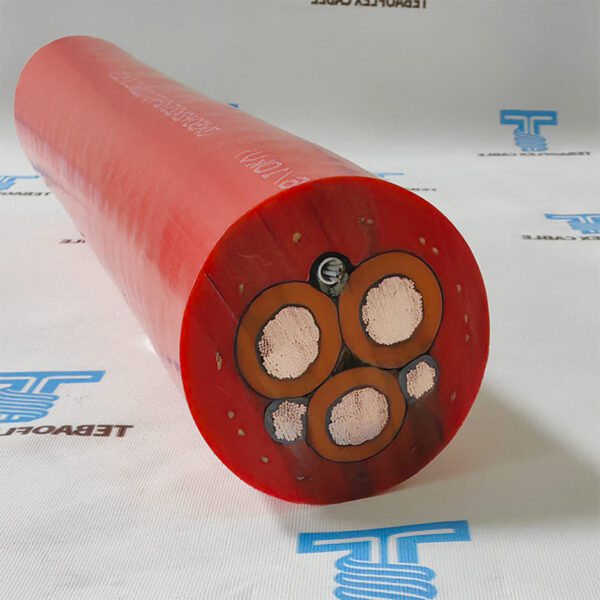
R-(N)TSCGEWOEU FO Cable is medium voltage reeling cable, it is design for connection of large material handling machines such as excavators, dumpers, mobile crushers in open-cast mines.
- Rated voltage3.6/6 KV – 20/35 KV
- StandardDIN VDE 0250-813
- ConductorClass 5 tinned or bare copper, IEC 60228
- InsulationSpecial EPDM rubber
- Outer sheathThermosetting compound 5GM5, Red
- Fiber optic module6, 12, 18 or 24 fibers
- Outer diameter40 – 91.4 mm
- Weight (approx.)2590 – 16590 kg/km
- R-(N)TSCGEWOEU FO Cable is medium voltage reeling cable, it is design for connection of large material handling machines such as excavators, dumpers, mobile crushers in open-cast mines. Flexible MV reeling cable suitable for high mechanical stresses in conjunction with mono-spiral reels and cylindrical reels. The fiber optic module is installed within a dedicated protective tube to prevent mechanical damage during continuous winding, bending, and torsional movement
- R-(N)TSCGEWOEU Cable is Standard Reeling Cable, it is designed purely for modern automated mining equipment, this integrated design eliminates the need for a separate fiber optic cable, reducing installation complexity while improving communication reliability.
Application & Features
Selection overview
R-(N)TSCGEWOEU+FO Cable Feature
The Caboe is specially designed flexible reeling cable with reduced dimensions for extremely high mechanical stresses occur in applications with monospiral reels and cylindrical reels, very high reeling speed, torsional stress. Also for connection of large material handling machines such as excavators, dumpers, crushers in open-cast mines. For use in wet or dry conditions, in industrial units, in underground and open-cast mining, in explosion-risk areas.
Standard R-(N)TSCGEWOEU Cable Feature
1.Flexible cable designed for high mechanical stresses, especially for applications with frequent winding and unwinding with concurrent tensile and torsion stress. The cable is used for conveyors and container cranes.
2.Specially designed flexible reeling cable with optimised dimensions for extremely high mechanical stresses.
3.Occur in applications with monospiral reels and cylindrical reels, very high reeling speed, torsional stress.
4.Also for connection of large material handling machines such as excavators, dumpers, crushers in open-cast mines.
5.For use in wet or dry conditions, in industrial units, in underground and open-cast mining, in explosion-risk areas.
For replacement planning on existing equipment, the port cable replacement checklist shows the reel geometry, drawing and acceptance information to gather before selecting a cable construction.

Specifications
Technical data
Voltage Electrical parameters
| Rated Voltage: | 3.6/6 KV | 6/10 KV | 8.7/15KV | 12/20 KV | 14/25 KV | 18/30 KV | 20/35 KV |
|---|---|---|---|---|---|---|---|
| Max. permissible operating voltage AC | 4.2/7.2 KV | 6.9/12 KV | 10.4/18KV | 13.9/24 KV | 17.3/30 KV | 20.8/36 KV | 24.2/42 KV |
| Max. permissible operating voltage DC | 5.4/10.8 KV | 9/18 KV | 13.5/27KV | 18/36 KV | 22.5/45 KV | 27/54 KV | 31.5/63 KV |
| AC test voltage – main cores | 11 KV (5Min) | 17 KV (5Min) | 24 KV (5Min) | 29 KV (5Min) | 36 KV (5Min) | 43 KV (5Min) | 50 KV (5Min) |
| AC test voltage – control cores | 2 KV | 2 KV | 2 KV | 2 KV | 2 KV | 2 KV | 2 KV |
Technical data
- Min. Distance With S-Type Directional Changes: 20×D
- Temperature range: Fixed: -40°C to +80°C, Flexed: -35°C to +80°C
- Max. operating temperature of the conductor : 90°C
- Maximum Short Circuit Temperature: +250°C
- Capacity: According to DIN VDE0298, Part 4
- Max. tensile load on the conductor: 20N/mm²
- Max. tensile load on the conductor during acceleration : 25N/mm²
- Torsional stress +/-: 100 °/m
- Bending radii min..: Acc. to DIN VDE 0298 part 3
- Travel speed: On rewinding: up to 100 m/min
- Reeling operation: up to 120 m/min
FO-Fiber Optic Structure
- Inner core diameter of fiber 9 μm, 62.5 μm or 50 μm;
Diameter over cladding 125 μm;
Diameter over coating 250 μm;
Designs up to 24 fibers available. - Fiber G50/125
Attenuation at 850 nm: <2 .8 dB/km
Attenuation at 1310 nm: <0 .8 dB/km
Bandwith at 850 nm: >400 MHz
Bandwith at 1300 nm: >1200 MHz
Nummerical aperture: 0.20 +/- 0.02 - Fiber G62 .5/125
Attenuation at 850 nm: <3 .3 dB/km
Attenuation at 1310 nm: <0 .9 dB/km
Bandwith at 850 nm: >400 MHz
Bandwith at 1300 nm: >600 MHz
Nummerical aperture: 0.275 +/- 0.02 - Fiber E9/125
Attenuation at 1310 nm: <0 .4 dB/km
Attenuation at 1550 nm: <0 .3 dB/km
Nummerical aperture: 0.14 +/- 0.02
Chromatic dispersion at 1310 nm: <3.5 ps/nm km
Technical and Electrical Characteristic R-(N)TSCGEWOEU Cable
R-(N)TSCGEWOEU FO 3.6/6 kV Parameter
| Number of cores x cross section | Conduc- tor diameter max. mm | Outer diameter min. mm | Outer diameter max. mm | Weight (approx.) kg/km | Permis- sible tensile force max. N | Con- ductor resis- tance at 20°C max. Ω/km | Nominal operating capacitance µF/km | Induc- tance nom. mH/ km | Current carrying capacity (1) A | Short Circuit Current (conduc- tor) kA |
|---|---|---|---|---|---|---|---|---|---|---|
| 3×25+2×25/2+FO | 7.1 | 40 | 43 | 2590 | 1500 | 0.7839 | 0.37 | 0.35 | 131 | 3.58 |
| 3×25+2×50/2+FO | 7.1 | 42.6 | 45.6 | 2900 | 1500 | 0.7839 | 0.37 | 0.38 | 131 | 3.58 |
| 3×35+2×25/2+FO | 8.4 | 41.6 | 44.6 | 2960 | 2100 | 0.554 | 0.43 | 0.32 | 162 | 5.01 |
| 3×35+2×50/2+FO | 8.4 | 44.5 | 47.5 | 3300 | 2100 | 0.554 | 0.43 | 0.35 | 162 | 5.01 |
| 3×50+2×25/2+FO | 10.1 | 42.8 | 45.8 | 3430 | 3000 | 0.386 | 0.49 | 0.28 | 202 | 7.15 |
| 3×50+2×50/2+FO | 10.1 | 46.4 | 49.4 | 3950 | 3000 | 0.386 | 0.49 | 0.31 | 202 | 7.15 |
| 3×70+2×35/2+FO | 11.8 | 46.4 | 49.4 | 4350 | 4200 | 0.272 | 0.55 | 0.27 | 250 | 10.01 |
| 3×70+2×50/2+FO | 11.8 | 49.8 | 53.8 | 4700 | 4200 | 0.272 | 0.55 | 0.29 | 250 | 10.01 |
| 3×95+2×50/2+FO | 13.8 | 51.5 | 55.5 | 5630 | 5700 | 0.206 | 0.63 | 0.26 | 301 | 13.59 |
| 3×120+2×70/2+FO | 15.5 | 55.2 | 59.2 | 6800 | 7200 | 0.161 | 0.7 | 0.25 | 352 | 17.16 |
| 3×150+2×70/2+FO | 17.4 | 59.2 | 63.2 | 7970 | 9000 | 0.129 | 0.76 | 0.25 | 404 | 21.45 |
| 3×185+2×95/2+FO | 19.2 | 64.4 | 68.4 | 9630 | 11100 | 0.106 | 0.82 | 0.24 | 461 | 26.46 |
| 3×240+2×120/2+FO | 22.1 | 70.6 | 74.6 | 12160 | 14400 | 0.0801 | 0.93 | 0.24 | 540 | 34.32 |
| 3×300+2×150/2+FO | 24.7 | 77.5 | 81.5 | 14880 | 18000 | 0.0641 | 1.03 | 0.23 | 620 | 42.9 |
R-(N)TSCGEWOEU FO 6/10 kV Parameter
| Number of cores x cross section | Conduc- tor diameter max. mm | Outer diameter min. mm | Outer diameter max. mm | Weight (approx.) kg/km | Permis- sible tensile force max. N | Con- ductor resis- tance at 20°C max. Ω/km | Nominal operating capacitance µF/km | Induc- tance nom. mH/ km | Current carrying capacity (1) A | Short Circuit Current (conduc- tor) kA |
|---|---|---|---|---|---|---|---|---|---|---|
| 3×25+2×25/2+FO | 7.1 | 41.3 | 44.3 | 2660 | 1500 | 0.7839 | 0.33 | 0.35 | 131 | 3.58 |
| 3×25+2×50/2+FO | 7.1 | 43.6 | 46.6 | 2900 | 1500 | 0.7839 | 0.33 | 0.38 | 131 | 3.58 |
| 3×35+2×25/2+FO | 8.4 | 42.9 | 45.9 | 3070 | 2100 | 0.554 | 0.38 | 0.33 | 162 | 5.01 |
| 3×35+2×50/2+FO | 8.4 | 45.2 | 48.2 | 3500 | 2100 | 0.554 | 0.38 | 0.35 | 162 | 5.01 |
| 3×50+2×25/2+FO | 10.1 | 44.1 | 47.1 | 3560 | 3000 | 0.386 | 0.43 | 0.29 | 202 | 7.15 |
| 3×50+2×50/2+FO | 10.1 | 47.8 | 50.8 | 3900 | 3000 | 0.386 | 0.43 | 0.32 | 202 | 7.15 |
| 3×70+2×35/2+FO | 11.8 | 47.7 | 50.7 | 4480 | 4200 | 0.272 | 0.49 | 0.28 | 250 | 10.01 |
| 3×70+2×50/2+FO | 11.8 | 51.2 | 55.2 | 5010 | 4200 | 0.272 | 0.49 | 0.3 | 250 | 10.01 |
| 3×70+2×50/2+FO | 13.8 | 52.8 | 56.8 | 5770 | 5700 | 0.206 | 0.56 | 0.27 | 301 | 13.59 |
| 3×120+2×70/2+FO | 15.5 | 56.4 | 60.4 | 6950 | 7200 | 0.161 | 0.62 | 0.25 | 352 | 17.16 |
| 3×150+2×70/2+FO | 17.4 | 61.9 | 65.9 | 8350 | 9000 | 0.129 | 0.67 | 0.25 | 404 | 21.45 |
| 3×185+2×95/2+FO | 19.2 | 65.7 | 69.7 | 9810 | 11100 | 0.106 | 0.73 | 0.24 | 461 | 26.46 |
| 3×240+2×120/2+FO | 22.1 | 73.3 | 77.3 | 12600 | 14400 | 0.0801 | 0.82 | 0.24 | 540 | 34.32 |
| 3×300+2×150/2+FO | 24.7 | 78.7 | 82.7 | 15090 | 18000 | 0.0641 | 0.91 | 0.23 | 620 | 42.9 |
R-(N)TSCGEWOEU FO 8.7/15 kV
| Number of cores x cross section | Conduc- tor diameter max. mm | Outer diameter min. mm | Outer diameter max. mm | Weight (approx.) kg/km | Permis- sible tensile force max. N | Con- ductor resis- tance at 20°C max. Ω/km | Nominal operating capacitance µF/km | Induc- tance nom. mH/ km | Current carrying capacity (1) A | Short Circuit Current (conduc- tor) kA |
|---|---|---|---|---|---|---|---|---|---|---|
| 3×25+2×25/2+FO | 7.1 | 43.6 | 46.6 | 2910 | 1500 | 0.7839 | 0.26 | 0.36 | 139 | 3.58 |
| 3×25+2×50/2+FO | 7.1 | 45.9 | 48.9 | 3250 | 1500 | 0.7839 | 0.26 | 0.38 | 139 | 3.58 |
| 3×35+2×25/2+FO | 8.4 | 43.9 | 46.9 | 3180 | 2100 | 0.554 | 0.29 | 0.33 | 172 | 5.01 |
| 3×35+2×50/2+FO | 8.4 | 47.5 | 50.5 | 3600 | 2100 | 0.554 | 0.29 | 0.35 | 172 | 5.01 |
| 3×50+2×25/2+FO | 10.1 | 47.5 | 50.5 | 3900 | 3000 | 0.386 | 0.33 | 0.31 | 215 | 7.15 |
| 3×50+2×50/2+FO | 10.1 | 51 | 55 | 4500 | 3000 | 0.386 | 0.33 | 0.32 | 215 | 7.15 |
| 3×70+2×35/2+FO | 11.8 | 52 | 56 | 5020 | 4200 | 0.272 | 0.37 | 0.3 | 265 | 10.01 |
| 3×70+2×50/2+FO | 11.8 | 52 | 56 | 5130 | 4200 | 0.272 | 0.37 | 0.3 | 265 | 10.01 |
| 3×95+2×50/2+FO | 13.8 | 56.2 | 60.2 | 6180 | 5700 | 0.206 | 0.41 | 0.28 | 319 | 13.59 |
| 3×120+2×70/2+FO | 15.5 | 61.3 | 65.3 | 7600 | 7200 | 0.161 | 0.45 | 0.27 | 371 | 17.16 |
| 3×150+2×70/2+FO | 17.4 | 65.3 | 69.3 | 8820 | 9000 | 0.129 | 0.5 | 0.27 | 428 | 21.45 |
| 3×185+2×95/2+FO | 19.2 | 69.1 | 73.1 | 10300 | 11100 | 0.106 | 0.54 | 0.26 | 488 | 26.46 |
| 3×240+2×120/2+FO | 22.1 | 76.6 | 80.6 | 13140 | 14400 | 0.0801 | 0.6 | 0.25 | 574 | 34.32 |
| 3×300+2×150/2+FO | 24.7 | 83.5 | 88.5 | 16040 | 18000 | 0.0641 | 0.66 | 0.25 | 660 | 42.9 |
R-(N)TSCGEWOEU FO 12/20kV
| Number of cores x cross section | Conduc- tor diameter max. mm | Outer diameter min. mm | Outer diameter max. mm | Weight (approx.) kg/km | Permis- sible tensile force max. N | Con- ductor resis- tance at 20°C max. Ω/km | Nominal operating capacitance µF/km | Induc- tance nom. mH/ km | Current carrying capacity (1) A | Short Circuit Current (conduc- tor) kA |
|---|---|---|---|---|---|---|---|---|---|---|
| 3×25+2×25/2+FO | 7.1 | 44.1 | 47.1 | 2980 | 1500 | 0.7839 | 0.23 | 0.36 | 139 | 3.58 |
| 3×25+2×50/2+FO | 7.1 | 47 | 50 | 3300 | 1500 | 0.7839 | 0.23 | 0.39 | 139 | 3.58 |
| 3×35+2×25/2+FO | 8.4 | 46.8 | 49.8 | 3480 | 2100 | 0.554 | 0.26 | 0.34 | 172 | 5.01 |
| 3×35+2×50/2+FO | 8.4 | 50.3 | 54.3 | 4000 | 2100 | 0.554 | 0.26 | 0.36 | 172 | 5.01 |
| 3×50+2×25/2+FO | 10.1 | 51.3 | 55.3 | 4370 | 3000 | 0.386 | 0.3 | 0.32 | 215 | 7.15 |
| 3×50+2×50/2+FO | 10.1 | 51.3 | 55.3 | 4450 | 3000 | 0.386 | 0.3 | 0.32 | 215 | 7.15 |
| 3×70+2×35/2+FO | 11.8 | 55 | 59 | 5370 | 4200 | 0.272 | 0.33 | 0.31 | 265 | 10.01 |
| 3×70+2×50/2+FO | 11.8 | 55 | 59 | 5480 | 4200 | 0.272 | 0.33 | 0.31 | 265 | 10.01 |
| 3×95+2×50/2+FO | 13.8 | 59.2 | 63.2 | 6550 | 5700 | 0.206 | 0.37 | 0.3 | 319 | 13.59 |
| 3×120+2×70/2+FO | 15.5 | 64.2 | 68.2 | 8000 | 7200 | 0.161 | 0.41 | 0.29 | 371 | 17.16 |
| 3×150+2×70/2+FO | 17.4 | 68.2 | 72.2 | 9240 | 9000 | 0.129 | 0.44 | 0.28 | 428 | 21.45 |
| 3×185+2×95/2+FO | 19.2 | 73.4 | 77.4 | 11010 | 11100 | 0.106 | 0.48 | 0.27 | 488 | 26.46 |
| 3×240+2×120/2+FO | 22.1 | 79.6 | 83.6 | 13650 | 14400 | 0.0801 | 0.54 | 0.26 | 574 | 34.32 |
| 3×300+2×150/2+FO | 24.7 | 86.4 | 91.4 | 16590 | 18000 | 0.0641 | 0.59 | 0.26 | 660 | 42.9 |
Standards & References
Applicable standards
Internation Standard
- Construction: DIN VDE 0250-813
- General Requirements: DIN VDE 0250-1
- Guide Use: DIN VDE 0298-3
- Electrical Tests: DIN VDE 0472-501, 503, 508
- Non-Electrical Tests: DIN VDE 0472-401. 402,602,303, 615
- Under Fire Condition Tests: DIN VDE 0472-803, 804
- Flame Retardant: VDE 0482-332-1-2,DIN EN 60332-1-2,IEC 60332-1
- Oil Resistant: HD/EN/IEC 60811-2-1.,DIN VDE0473-811-2-1
- Water resistance: EN 50525-2-21 (HD 22.16)
- Weather resistance: Unrestricted use outdoors and indoors, resistant to ozone, UV and moisture
Construction
Material and build-up
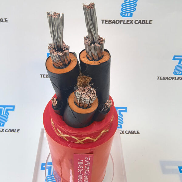
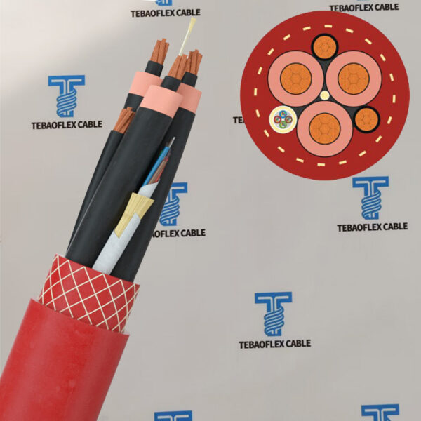
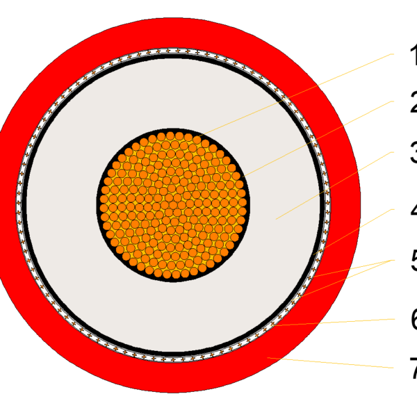
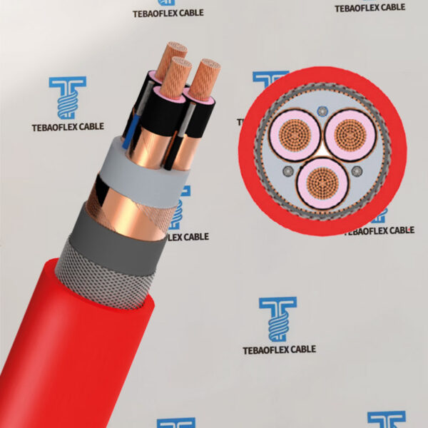
MV R-(N)TSCGEWOEU with FO Reeling Cable Construction
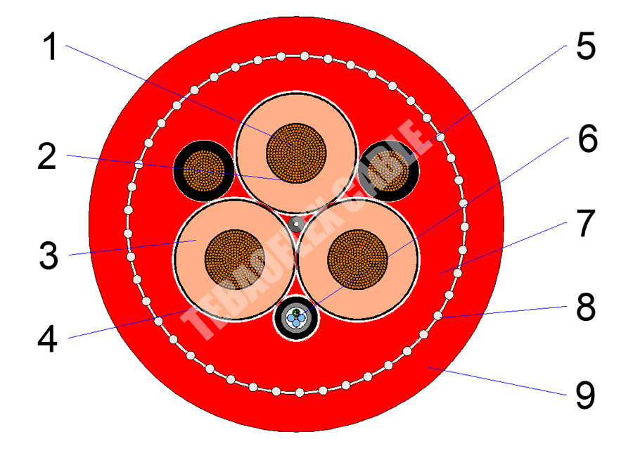
- Conductor: Annealed class 5 flexible stranded tinned or bare copper acc. to, IEC 60228.
- Separator: Semi-conductive tape between the power conductor and insulation and between earth conductor
- Conductor Screen: Semi-conductive layer of special rubber
- Insulation: Special EPDM rubber
- Insulation Screen: Semi-conductive, special strippable layer
- Earth Conductor: Class 5 tinned or bare copper with extruded special semi-conductive rubber compound
- Fiber Optic Module: A-D(ZN)13Y 6, 12, 18 or 24 fibers G50/125, G62,5/125 or E9/125
Fiber coding: Color coding of the fibers and buffering tube for identification of the fiber type
Fiber covering: Loose tube with filling compound, Basic material: ETFE, Compound: 7YI 1, Natural color - Inner Sheath: A special synthetic thermosetting compound type 5GM3
- Anti-Torsion Braid: Braid of polyamide threads between inner and outer sheath
- Outer Sheath: Special synthetic thermosetting compound 5GM5, Red
MV R-(N)TSCGEWOEU Reeling Cable Construction
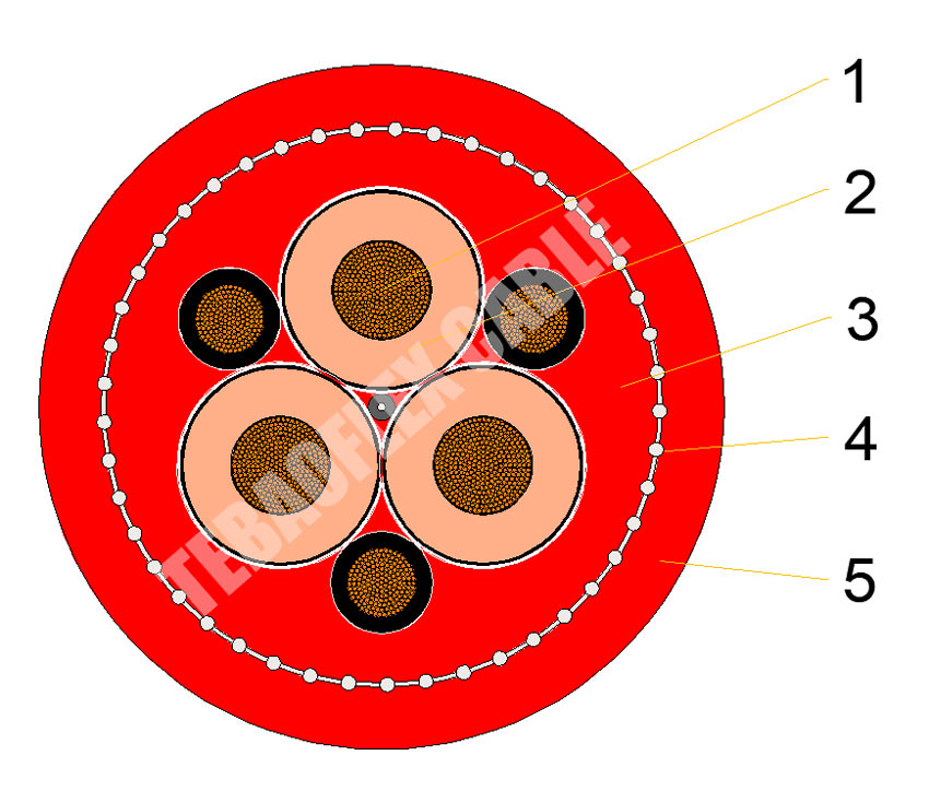
- Conductors: Annealed flexible stranded tinned or bare copper conductor class 5 to IEC 60228.
Type of conductor design: opposite-lay with special length of lay. - Separator: Semi-conductive tape between the power conductor and insulation and between earth conductor and semi-conductive layer
- Conductor screen: Semi-conductive layer of special rubber
- Insulation: Special EPDM rubber+Semi-conductive, special strippable layer over insulation of power cores.
Maximum resistivity of semi-conductive layers -200 [Ω x m] - Earth conductor: Tinned or bare copper conductor class 5 to IEC 60228 with extruded special semi-conductive rubber compound.
- Core arrangement: Power conductors and earth conductor (split into 3 parts) laid up around central semi-conductive filler.
Anti-adhesion graphite over assembled conductors - Inner sheath: A special synthetic thermosetting compound type 5GM3 acc. to DIN VDE 0207/21, Red
- Anti-torsion braid: Braid of polyamide threads between inner and outer sheath
- Outer sheath: Special synthetic thermosetting compound, type 5GM5, Red.
More Details
Comparison and references
Difference between R-(N)TSCGEWOEU and R-(N)TSCGEWOEU FO Reeling Cable
Both R-(N)TSCGEWÖU and R-(N)TSCGEWÖU FO are high-performance medium-voltage flexible reeling cables designed according to DIN VDE 0250-813 for heavy-duty mining and bulk material handling equipment. They share the same power transmission structure, insulation system, and mechanical performance. The primary difference is that the FO (Fiber Optic) version integrates optical fibers within the cable, enabling simultaneous power supply and high-speed data communication.
Application Difference Between R-(N)TSCGEWOEU and R-(N)TSCGEWOEU FO
R-(N)TSCGEWOEU Reeling Cable: Recommended for:
- Electric shovels
- Bucket-wheel excavators
- Mobile crushers
- Stackers
- Reclaimers
- Cable reel systems
- Conveyor equipment)
These applications primarily require reliable medium-voltage power transmission
R-(N)TSCGEWOEU FO: Recommended for intelligent mining equipment requiring both power and communication.
- Autonomous mining equipment
- Smart electric shovels
- Intelligent conveyor systems
- Automated stackers
- Bucket-wheel excavators
- Open-pit mining automation
- Port container cranes
- High-speed cable reel systems
- Digital mining operations
Difference Between Choose R-(N)TSCGEWOEU FO and R-(N)TSCGEWOEU
- Choose R-(N)TSCGEWÖEU if your equipment only requires reliable medium-voltage power transmission and communication is handled through separate cables.
- Choose R-(N)TSCGEWÖEU with FO if your mining equipment requires both power supply and high-speed data communication within a single cable. This option is particularly suitable for automated mines, intelligent conveyor systems, remote monitoring, and digitally connected mining operations, where reducing installation complexity and improving communication reliability are key priorities
MV R-(N)TSCGEWOEU Cable Packaging Standard
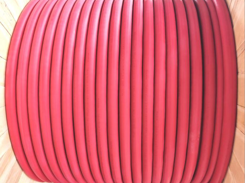
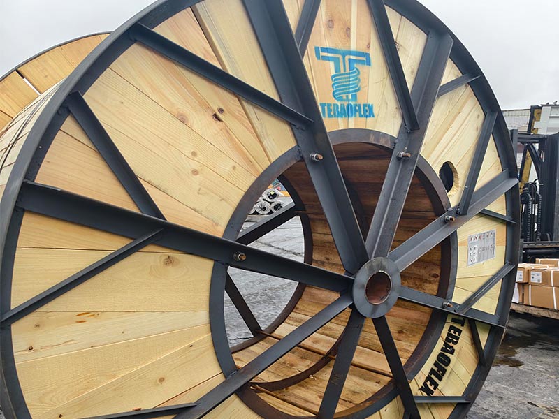
This medium-voltage reeling cable is typically packaged in wooden drums (standard) or spools/cartons (small orders), with strict protection for ends and outer sheath.
1. Standard Packaging (Bulk Order, ≥100m)
- Reel/Drum: Plywood or solid wooden drum, diameter and barrel width based on cable OD and length (common: 500m/1000m per drum)
- Cable Winding: Tightly and neatly wound, no crossing or loose loops; min. bending radius ≥20× cable OD.
- End Sealing: Both ends sealed with heat-shrink caps or waterproof plastic caps to prevent moisture ingress.
- Protection: Wrapped with PE foam or waterproof film; outer sheath protected against abrasion and UV.
- Labeling: Drum marked with type, voltage, length, batch, net/gross weight, manufacturer
2. Small Quantity/Sample Packaging (<100m)
- Spool/Roll: Small plastic/wooden spool or coil.
- Inner Pack: EPE foam wrap + PE bag for moisture and dust protection.
- Outer Pack: K=K corrugated carton (6–7mm thick) with corner protectors; sealed with waterproof tape
3. Mandatory Markings (Front & Side of Wooden Drum)
- Cable Type: MV R-(N)TSCGEWOEU
- Rated Voltage (kV)
- Conductor Size (mm²)
- Length (m)
- Batch No.
- Production Date
- Net Weight (kg)
- Gross Weight (kg)
- Drum Size: diameter × width (mm)
- Manufacturer Name & Address
- Country of Origin: China
Request this cable.
Send the core configuration, length and application details.
Quality Assurance
Testing at every stage in our own workshop and laboratory, from incoming copper to the packed drum.
Raw Material Inspection
Every batch of copper rod, rubber compound and reinforcing material is checked before it reaches the line.
- Copper: conductor resistance, elongation and surface condition on incoming rod and drawn wire
- EPR, CPE, PUR and silicone compounds: hardness, tensile strength, elongation and ageing samples from each mix
- Suppliers and batch numbers are recorded so every drum can be traced back to its materials
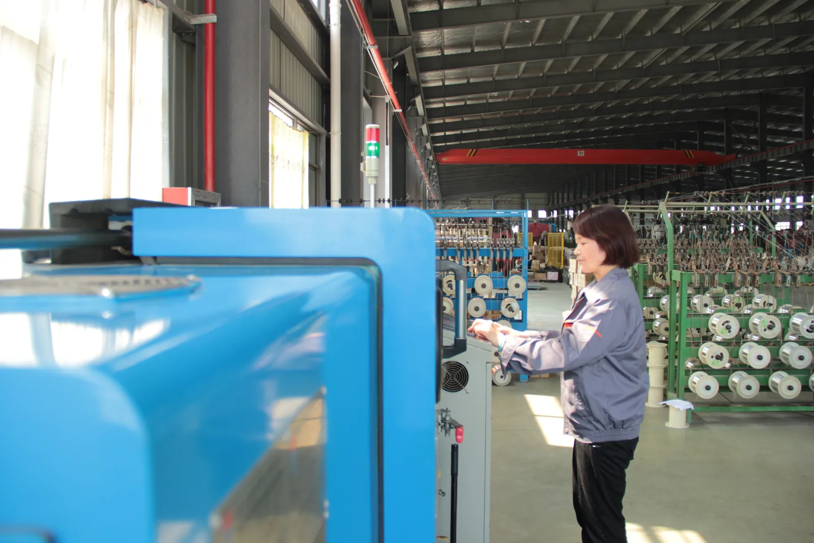
Manufacturing Process Control
Stranding, insulation extrusion, core assembly and sheathing run under recorded process parameters.
- Class 5/6 stranding with lay length and tension monitored for trailing and reeling flexibility
- Continuous-vulcanisation extrusion with wall thickness and spark tests logged on every length
- Operators sign off each stage before the cable moves to the next machine
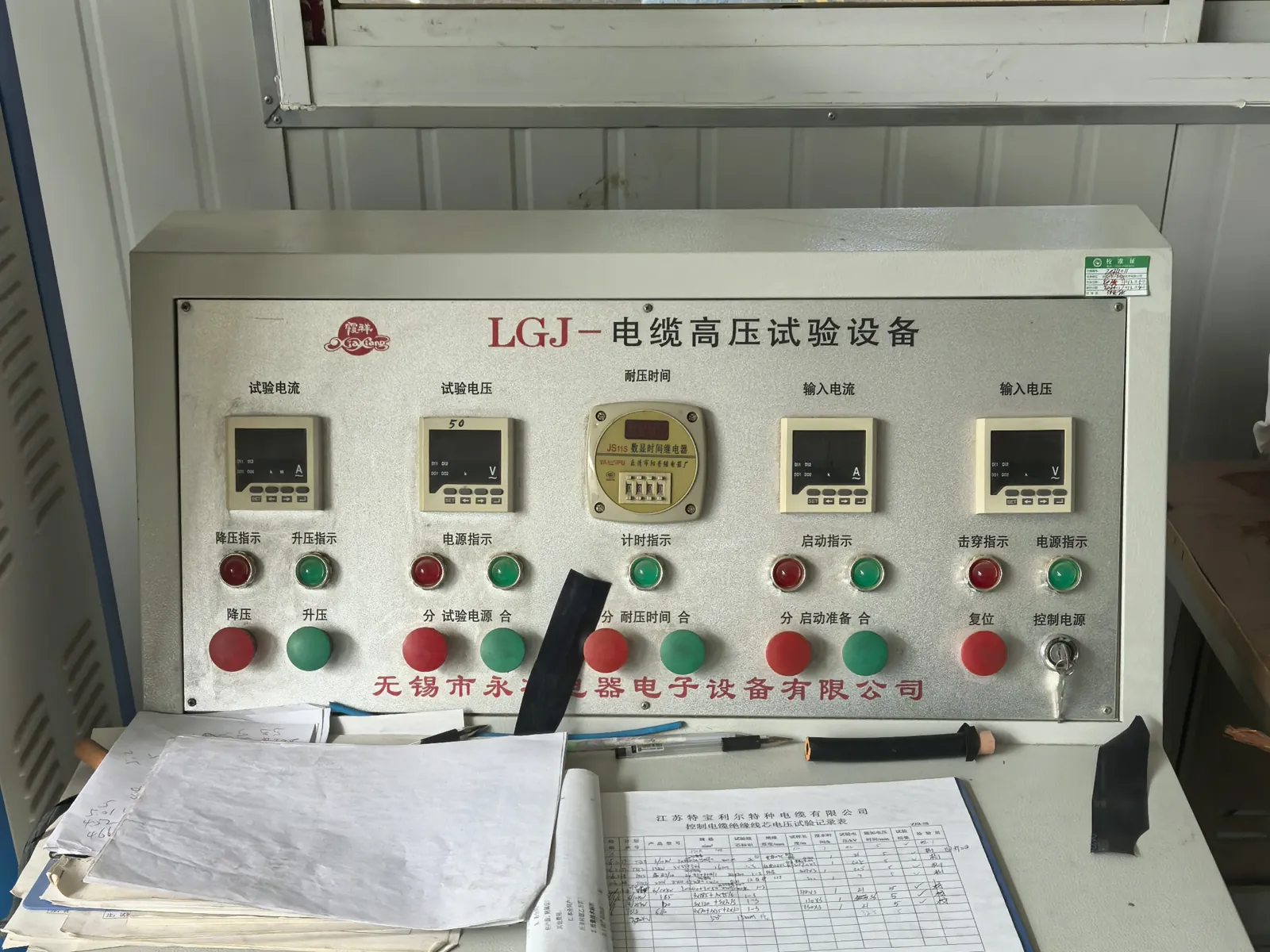
Electrical Testing
Finished lengths go through the routine tests required by the referenced VDE, ICEA, IEC or NEK standard.
- Conductor resistance and insulation resistance on every length
- Voltage withstand (3.5 kV and higher) and partial-discharge measurement in the shielded HV laboratory
- Screen and pilot-core continuity checks for mining and reeling constructions
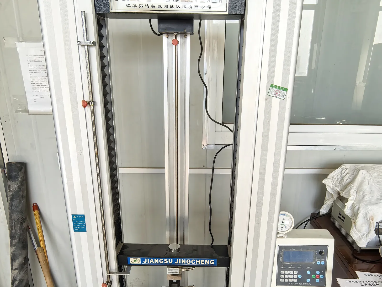
Mechanical and Ageing Tests
Samples from production are tested for the duty a mining, crane or submersible cable will actually see.
- Tensile strength and elongation of insulation and sheath before and after ageing
- Hot-set, ozone, oil-immersion and low-temperature bending tests
- Constant-temperature water bath for insulation resistance of submersible constructions
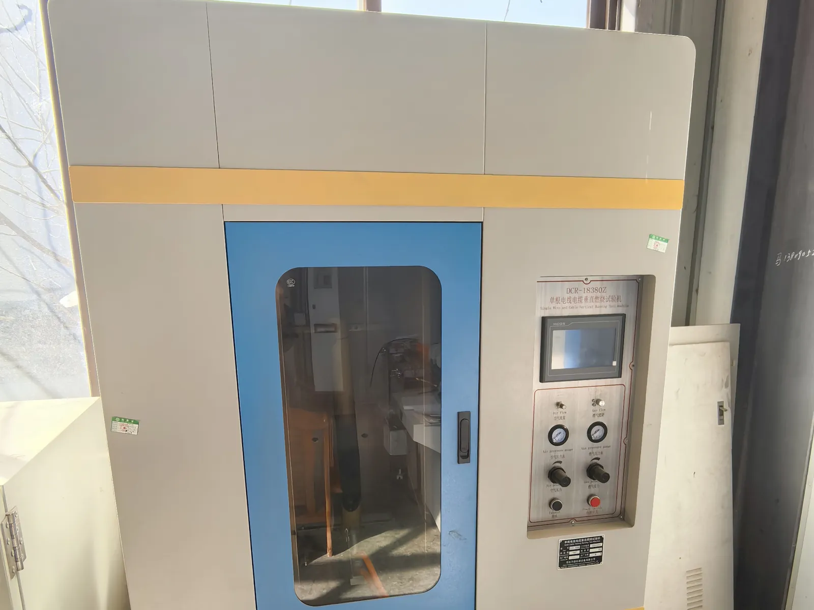
Flame Test and Final Inspection
Before packing, the cable is checked against the order and the flame-performance requirement of its standard.
- Single-cable vertical flame test to IEC 60332-1-2 where specified
- Metre marking, printing, drum length and appearance inspection
- Test report and packing list issued with every shipment
Related products
-
(N)TSCGEWÖU Submersible ABT FO(LWL) Mining Trailing Cable
-
(N)TMCGCW11Y Cable | Medium Voltage Flexible Reeling Cable
-
2000V 4 0 535 DLO Diesel Locomotive Cable 90°C EPR-CPE RHH RHW-2 for Mining
-
NTMCGCWOEU / (N)TMCGCWOEU 6-30kV Single-Core EPR Heavy-Duty Rubber Cable
-
(N)TMCGETMPU vs RIT-(N)TMCGETMPU Portable Trailing Cable
-
NTMTWOEU Mine Hoist Cable Manufacturer | Underground Mining Lift Cable
-
(N)3GHSSHCH LSZH Tunnelling & Underground Mining Cable
-
MV Motor RTS (N)TSCGEWTOEUS OFE Reeling Cable 3×70 + 3×35/3 + (20×2.5)C + 24FO (9/125)
Need Pricing for This Cable?
Tell us the length, cores, cross-section and delivery country and we will reply with a quotation and datasheet.