
YnKGY-żo 0.6/1 kV PVC Mining Power Cable
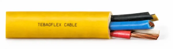
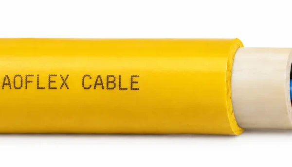
YnKGY-żo is a 0.6/1 kV PVC mining power cable with a green-yellow protective conductor and a yellow flame-retardant PVC sheath.
- Solid Class 1 or stranded Class 2 copper; 10 mm² is Class 2.
- 3-, 4- and 5-core configurations, 1.5–10 mm².
- Operating range: -30 to +70 °C.
- Minimum installation temperature: -5 °C.
- Minimum bending radius: 10 × OD.
- Test voltage: 3.5 kV.
Send the full configuration, installation conditions, length and quantity for a technical quotation.
YnKGY-żo Mining Power Cable with a Protective Core
YnKGY-żo is a 0.6/1 kV copper mining power cable with special PVC insulation, a yellow flame-retardant PVC sheath and a green-yellow protective conductor. It supplies electrical equipment in open-pit, strip and underground mines without an explosion hazard, including methane-free areas with class A coal dust hazard.
The range includes three-, four- and five-core constructions from 1.5 to 10 mm². The total core count includes the protective conductor: a four-core cable contains three other conductors plus the green-yellow core. Match that complete arrangement to the circuit diagram before choosing conductor size, especially when replacing a cable identified only by an incomplete marking.
Solid Class 1 or stranded Class 2 copper defines this power-cable construction; the 10 mm² configurations specifically use Class 2 conductors. The conductor choice and installation geometry should be checked together with the terminals, available bend space and required sheath color.
- Separate service from installation: the operating range is -30 to +70 °C, while installation requires at least -5 °C.
- Plan the cable entry: allow the specified 10 × outside-diameter bending radius and match glands to the maximum OD.
- Identify the protective circuit: the green-yellow core is included in the published three-, four- or five-core designation.
Use the dimension and electrical tables to prepare a configuration-specific inquiry. Browse our mining cable range for other constructions, or download the YnKGY-żo datasheet.
Construction
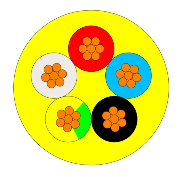
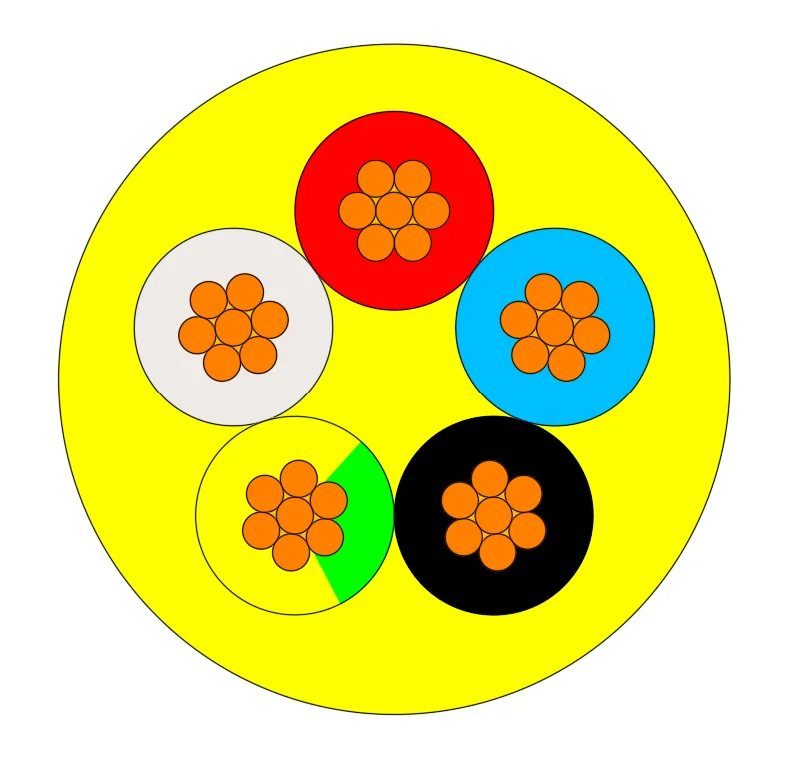
YnKGY-żo combines insulated power and protective conductors within a yellow PVC sheath. The five-core cross-section illustrates the natural, red, blue, black and green-yellow core identification.
| Component | Construction | Selection note |
|---|---|---|
| Conductors | Copper, solid Class 1 or stranded Class 2 to PN-EN 60228 | 10 mm² configurations use Class 2 conductors. |
| Core insulation | Special PVC | Select the correct total core count and conductor area. |
| Protective conductor | Green-yellow insulated conductor | Included in the total cable core count. |
| Three-core identification | Natural, red and green-yellow | Two other cores plus one protective core. |
| Four-core identification | Natural, red, blue and green-yellow | Three other cores plus one protective core. |
| Five-core identification | Natural, red, blue, black and green-yellow | Four other cores plus one protective core. |
| Core assembly | Twisted power and protective conductors | Match the arrangement to the equipment circuit diagram. |
| Outer sheath | Special flame-retardant PVC; yellow | Confirm the required sheath marking with the order. |
Match the conductor to the termination
Confirm whether solid Class 1 or stranded Class 2 conductors are required for the selected size, and match the terminal design to that conductor construction. Specify Class 2 for the 10 mm² configurations. A total core count includes the protective conductor; it is not an additional core outside the stated configuration.
Identify the sheath construction before substitution
Specify the complete YnKGY-żo designation when comparing cables with the same conductor area. A requirement for a separate inner sheath, a screen or armor calls for a construction review before the replacement is ordered.
Applications
YnKGY-żo supplies electrical equipment in open-pit, strip and underground mines without an explosion hazard, including methane-free areas with class A coal dust hazard. Select the cable against the site classification and the equipment wiring schedule.
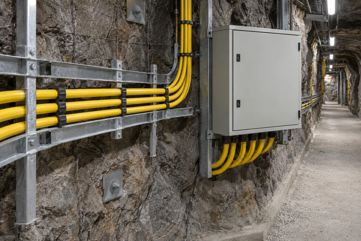
- Mine equipment power circuits: match the number of insulated conductors and the protective conductor to the circuit.
- Installed cable routes: check supports, entry clearances and the required bend geometry before specifying the cable length.
- Replacement planning: compare the complete model, core count, conductor area and sheath construction with the existing connection.
Plan cold-weather installation separately
The -30 °C operating limit does not permit installation at that temperature. Plan laying and termination for at least -5 °C, and confirm site handling conditions before work begins. Maintain a minimum bend radius of 10 × the cable outside diameter at route changes and equipment entries.
Describe any movement and exposure
For a route involving continuous reeling, repeated flexing, immersion, oil or severe mechanical loading, send the full operating duty for engineering selection. The core class and flame-test references alone do not establish suitability for those conditions.
Count the protective conductor in the connection plan
A three-core designation includes the green-yellow protective core. Confirm the number of other circuit conductors required before selecting the core count; a voltage match alone does not confirm the cable arrangement.
Specifications
Select the exact YnKGY-żo configuration below. OD means the finished cable outside diameter. Dimensions are maximum outside diameters; use the configuration-specific weight when planning lengths and handling.
| Parameter | Value |
|---|---|
| Rated voltage U₀/U | 0.6/1 kV |
| Test voltage | 3.5 kV |
| Conductor construction | Copper, Class 1 or Class 2; 10 mm² is Class 2 |
| Core counts | 3, 4 or 5, including the green-yellow protective core |
| Listed conductor areas | 1.5, 2.5, 4, 6 and 10 mm² |
| Operating temperature range | -30 to +70 °C |
| Minimum installation temperature | -5 °C |
| Minimum bending radius | 10 × OD |
| Outer sheath color | Yellow |
Dimensions and ordering configurations
The designation gives the total core count × conductor area in mm². For example, YnKGY-żo 4x2.5 contains four 2.5 mm² conductors, including the green-yellow protective conductor.
| Model + configuration (mm²) | Max. OD (mm) | Weight (kg/km) |
|---|---|---|
| YnKGY-żo 3x1.5 | 10.2 | 153 |
| YnKGY-żo 4x1.5 | 11.1 | 180 |
| YnKGY-żo 5x1.5 | 11.8 | 215 |
| YnKGY-żo 3x2.5 | 11.0 | 195 |
| YnKGY-żo 4x2.5 | 12.0 | 235 |
| YnKGY-żo 5x2.5 | 12.9 | 280 |
| YnKGY-żo 3x4 | 12.9 | 280 |
| YnKGY-żo 4x4 | 14.2 | 345 |
| YnKGY-żo 5x4 | 15.2 | 410 |
| YnKGY-żo 3x6 | 13.9 | 355 |
| YnKGY-żo 4x6 | 15.4 | 440 |
| YnKGY-żo 5x6 | 16.6 | 525 |
| YnKGY-żo 3x10* | 16.4 | 520 |
| YnKGY-żo 4x10* | 18.1 | 655 |
| YnKGY-żo 5x10* | 19.6 | 790 |
* 10 mm² conductors are Class 2 according to PN-EN 60228.
Power-conductor electrical data
Assess the listed current values against the installation method, ambient conditions, grouping and load profile before selecting the conductor area. The short-circuit values below apply for one second at the maximum long-term conductor temperature; they are separate from continuous current capacity.
| Conductor area (mm²) | Resistance (Ω/km) | Inductance (mH/km) | Reactance (Ω/km) | Reference current (A) | 1-second short circuit (kA) |
|---|---|---|---|---|---|
| 1.5 | 12.1 | 0.34 | 0.107 | 19 | 0.17 |
| 2.5 | 7.41 | 0.32 | 0.099 | 27 | 0.29 |
| 4 | 4.61 | 0.32 | 0.100 | 37 | 0.46 |
| 6 | 3.08 | 0.30 | 0.095 | 47 | 0.69 |
| 10 | 1.83 | 0.28 | 0.089 | 62 | 1.15 |
For quotation, provide the circuit current, protective-device clearing time and route conditions so the cable size and protection arrangement can be reviewed together.
Standards
YnKGY-żo uses the following conductor and flame-performance references. Include the required inspection documents and cable marking in the inquiry.
| Reference or test | Requirement / role |
|---|---|
| PN-EN 60228 | Class 1 solid or Class 2 stranded copper conductors; 10 mm² configurations use Class 2. |
| PN-EN 60332-1 | Single-cable flame-performance test reference. |
| PN-EN 60332-3-24 / IEC 60332-3 | Bunched-cable flame-performance test references. |
| Oxygen index | Greater than 29. |
| Voltage test | 3.5 kV. |
The yellow PVC sheath is selected for flame performance. Confirm the installation location and required documentation as part of the order, including the applicable mine area classification. Download the YnKGY-żo technical datasheet for the complete construction and numerical tables.
Request Quote
Send the YnKGY-żo configuration, required voltage, length and quantity, installation duty, equipment connection details and sheath color. Include the protective-core, screen or armor requirements that apply to the selected construction, together with inspection requirements.
You can also use our technical contact form.
Quality Assurance
Testing at every stage in our own workshop and laboratory, from incoming copper to the packed drum.
Raw Material Inspection
Every batch of copper rod, rubber compound and reinforcing material is checked before it reaches the line.
- Copper: conductor resistance, elongation and surface condition on incoming rod and drawn wire
- EPR, CPE, PUR and silicone compounds: hardness, tensile strength, elongation and ageing samples from each mix
- Suppliers and batch numbers are recorded so every drum can be traced back to its materials
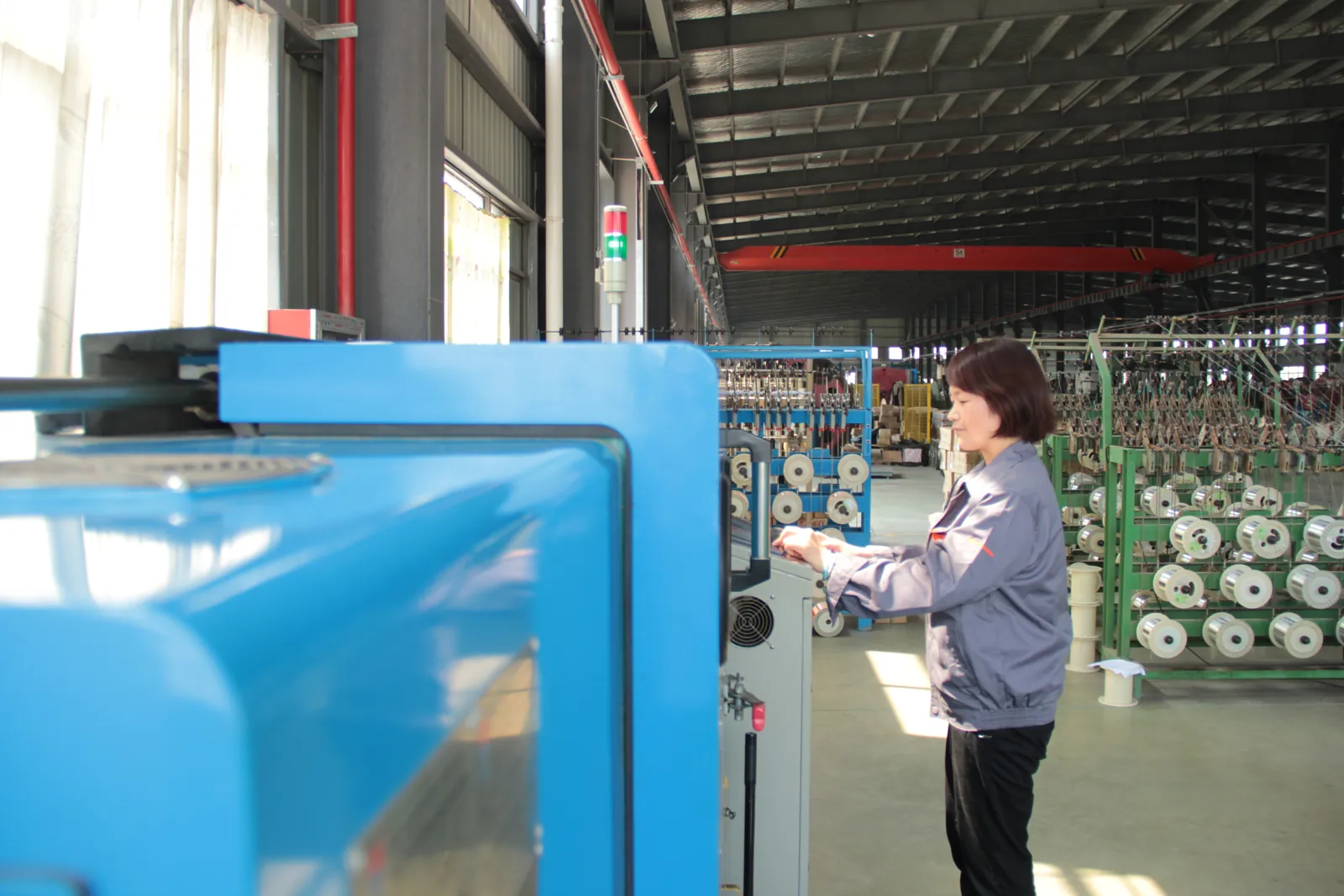
Manufacturing Process Control
Stranding, insulation extrusion, core assembly and sheathing run under recorded process parameters.
- Class 5/6 stranding with lay length and tension monitored for trailing and reeling flexibility
- Continuous-vulcanisation extrusion with wall thickness and spark tests logged on every length
- Operators sign off each stage before the cable moves to the next machine
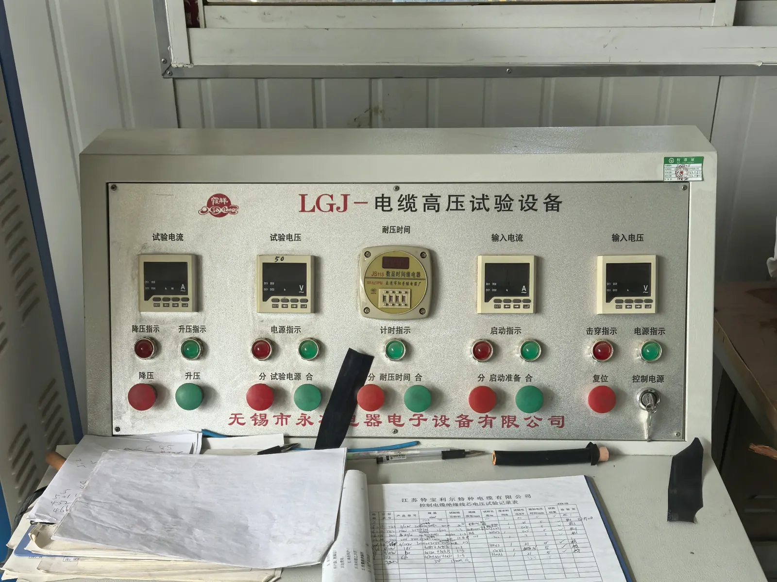
Electrical Testing
Finished lengths go through the routine tests required by the referenced VDE, ICEA, IEC or NEK standard.
- Conductor resistance and insulation resistance on every length
- Voltage withstand (3.5 kV and higher) and partial-discharge measurement in the shielded HV laboratory
- Screen and pilot-core continuity checks for mining and reeling constructions
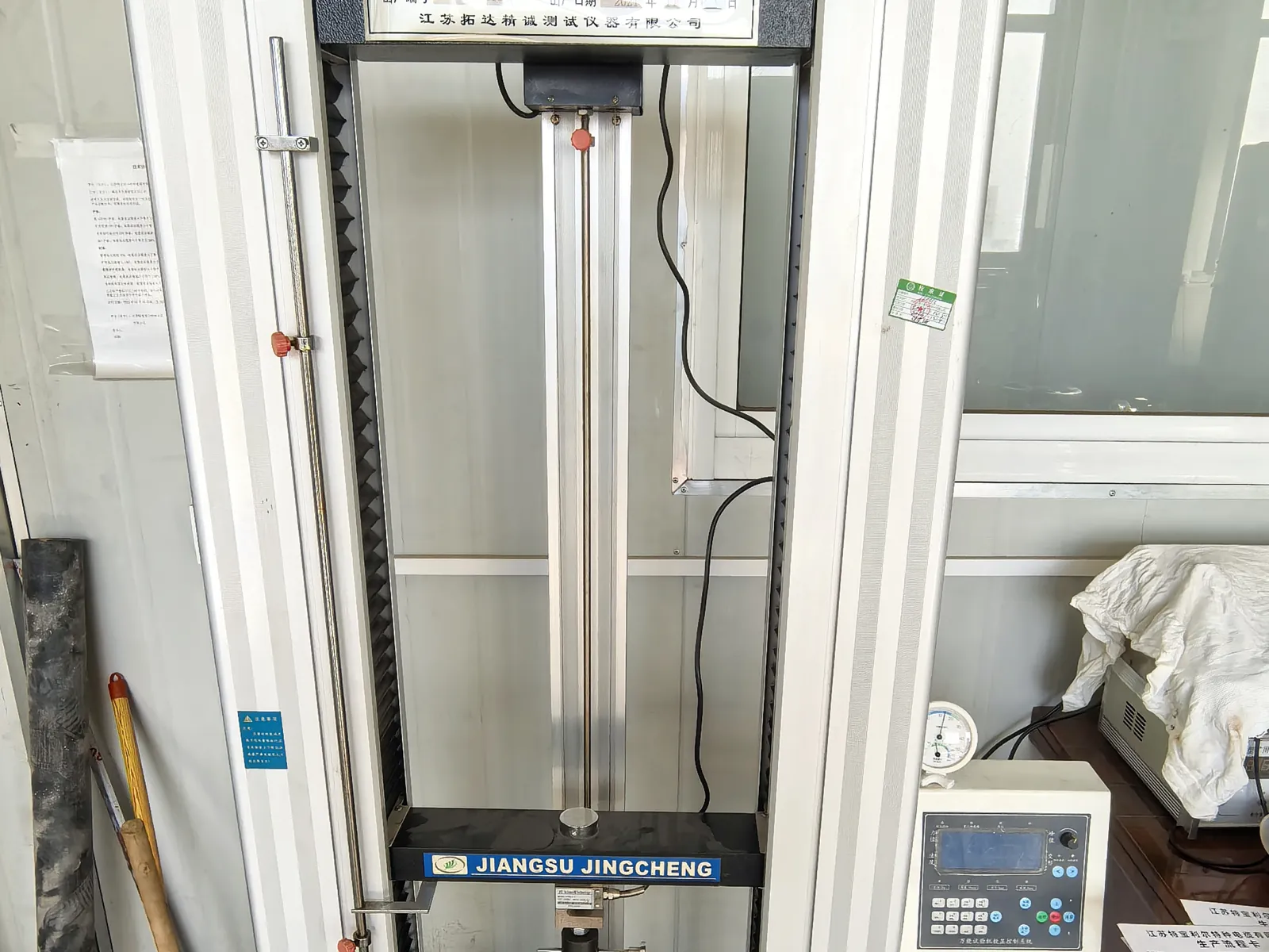
Mechanical and Ageing Tests
Samples from production are tested for the duty a mining, crane or submersible cable will actually see.
- Tensile strength and elongation of insulation and sheath before and after ageing
- Hot-set, ozone, oil-immersion and low-temperature bending tests
- Constant-temperature water bath for insulation resistance of submersible constructions
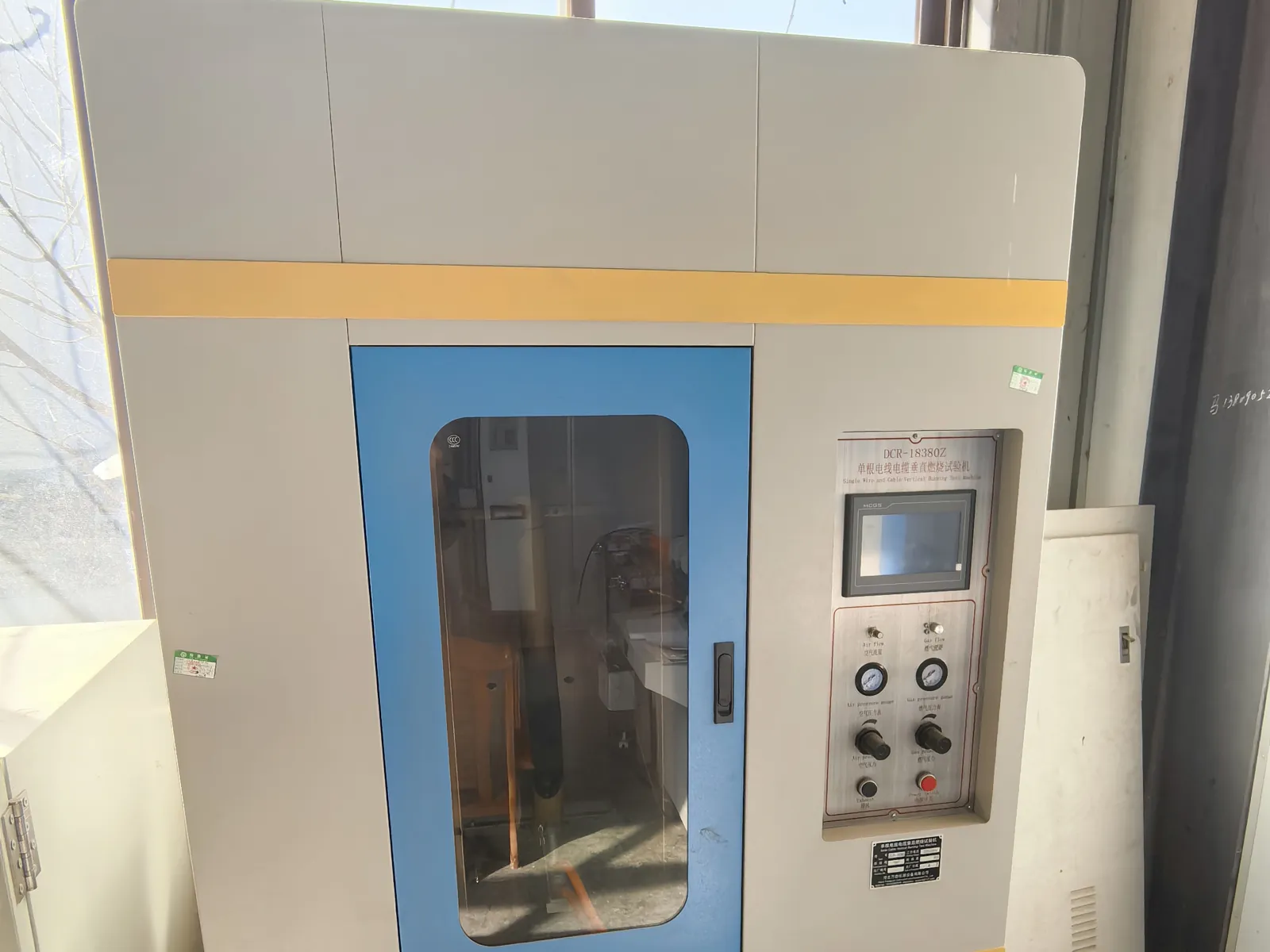
Flame Test and Final Inspection
Before packing, the cable is checked against the order and the flame-performance requirement of its standard.
- Single-cable vertical flame test to IEC 60332-1-2 where specified
- Metre marking, printing, drum length and appearance inspection
- Test report and packing list issued with every shipment
You may also like…
Related products
Need Pricing for This Cable?
Tell us the length, cores, cross-section and delivery country and we will reply with a quotation and datasheet.