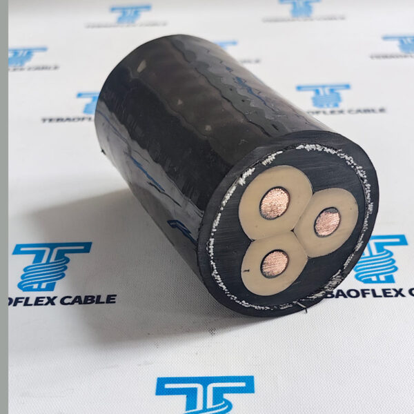
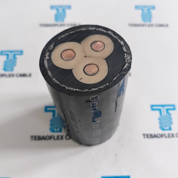
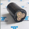
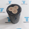
(N)TSCGEWÖU Submersible ABT FO(LWL) Mining Trailing Cable
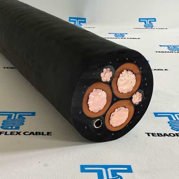
(N)TSCGEWÖU Cable for fixed energy distribution in mines.
- Voltage (Uo/U)3.6/6kV to 12/20kV
- StandardDIN VDE 0250
- Phase conductorClass 5 Flexible Stranded Tinned Copper
- InsulationRubber Compound
- Phase cross section25 – 185 mm2
- Overall diameter39.9 – 75.5 mm
- Nominal weight2390 – 10700 kg/km
- Submersible versionUp to 300 metres
(N)TSCGEWÖU Cable for fixed energy distribution in mines.
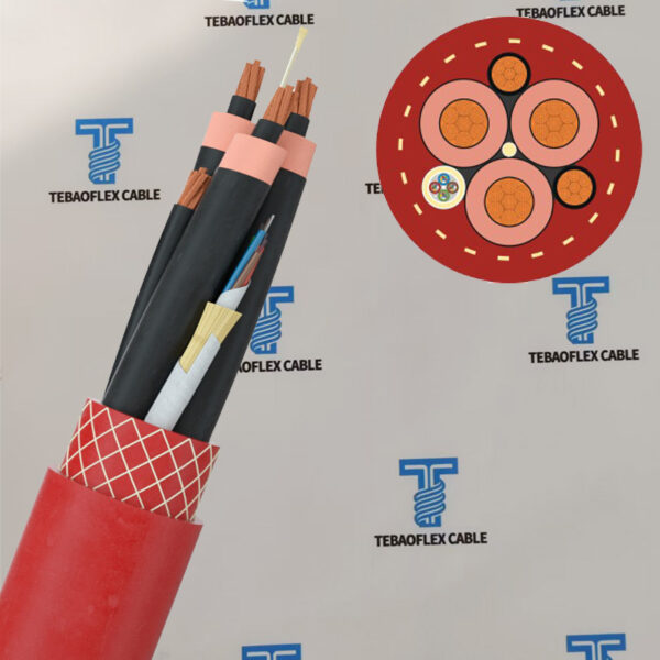
(N)TSCGEWÖU FO Cable for high and extreme mechanical stresses, including torsional stress, deflection into different planes.
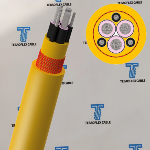
(N)TSCGEWÖU ATB Cable for heavy mobile equipment such as drag lines, shovels, dredges, drills, under extreme mechanical stresses
(N)TSCGEWÖUsubmersible Cable for in salty and brackish water immersion up to 300 metres under high mechanical stress
All these (N)TSCGEWÖU Mining Trailing Cable for mining, drilling and tunnelling trailing operations for use in surface or underground installations, It is a medium-voltage, flexible, heavy-duty reel/tow cable conforming to DIN VDE 0250, mainly designed for high mechanical stress scenarios such as mining, tunnels, dredging, and underwater equipment. It has five core characteristics: waterproof, oil-resistant, flame-retardant, torsion-resistant, and highly flexible.
Application & Features
Selection overview
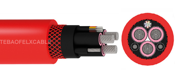
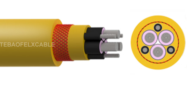
TEBAOFLEX (N)TSCGEWÖU FO(LWL) fibre optics:Flexible reeling cable with integrated fibre optic wires for high and extreme mechanical stresses, including torsional stress, deflection into different planes, and high reeling speed. Suitable for indoor and outdoor applications.
TEBAOFLEX (N)TSCGEWÖU ATB Cable higher flexibility: Flexible cable for energy supply to heavy mobile equipment such as drag lines, shovels, dredges, drills, under extreme mechanical stresses and abrasions during trailing operations in opencast mines
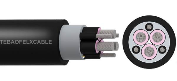
TEBAOFLEX (N)TSCGEWÖU submersible Cable for flexible supply cable for permanent use in salty and brackish water immersion up to 300 metres under high mechanical stress. For applications such as pumps, dredges and floating docks. It is suitable for trailing operations of opencast mining equipment
Specifications
Technical data
(N)TSCGEWÖU Submersbile /FO(DWL)/ABT Cable Technical Data
(N)TSCGEWÖU Submersible Cable
| VOLTAGE kV | NO. OF CORES (PHASE + EARTH) | NOMINAL CROSS SECTIONAL AREA | CONDUCTOR DIAMETER | MINIMUM OVERALL DIAMETER | MAXIMUM OVERALL DIAMETER | MAXIMUM TENSILE LOAD | NOMINAL WEIGHT | |
|---|---|---|---|---|---|---|---|---|
| mm2 | mm | mm | mm | N | kg/km | |||
| Phase Conductor | Earth Conductor | |||||||
| 3.6/6 | 3+3 | 25 | 25/3 | 6.8 | 39.9 | 41.6 | 1500 | 2580 |
| 3.6/6 | 3+3 | 35 | 25/3 | 7.8 | 42.9 | 44.6 | 2100 | 3080 |
| 3.6/6 | 3+3 | 50 | 3/25 | 9.4 | 46 | 47.7 | 3000 | 3710 |
| 3.6/6 | 3+3 | 70 | 35/3 | 11.2 | 49.8 | 51.6 | 4200 | 4670 |
| 3.6/6 | 3+3 | 95 | 50/3 | 12.7 | 55.8 | 57.6 | 5700 | 5880 |
| 3.6/6 | 3+3 | 120 | 70/3 | 14.4 | 59.6 | 61.4 | 7200 | 7140 |
| 3.6/6 | 3+3 | 150 | 70/3 | 16.3 | 66 | 68.3 | 9000 | 8690 |
| 3.6/6 | 3+3 | 185 | 95/3 | 17.6 | 67.9 | 70.2 | 11100 | 9890 |
| 6/10 | 3+3 | 25 | 25/3 | 6.8 | 39.9 | 42.2 | 1500 | 2620 |
| 6/10 | 3+3 | 35 | 25/3 | 7.8 | 42.9 | 45.2 | 2100 | 3120 |
| 6/10 | 3+3 | 50 | 25/3 | 9.4 | 46 | 48.3 | 3000 | 3750 |
| 6/10 | 3+3 | 70 | 35/3 | 11.2 | 49.8 | 52.2 | 4200 | 4710 |
| 6/10 | 3+3 | 95 | 50/3 | 12.7 | 55.8 | 58.2 | 5700 | 5920 |
| 6/10 | 3+3 | 120 | 70/3 | 14.4 | 59.6 | 62.1 | 7200 | 7180 |
| 6/10 | 3+3 | 150 | 70/3 | 16.3 | 66 | 69 | 9000 | 8730 |
| 6/10 | 3+3 | 185 | 95/3 | 17.6 | 67.9 | 70.9 | 11100 | 9930 |
| 8.7/15 | 3+3 | 35 | 25/3 | 7.8 | 48.8 | 50.6 | 2100 | 3680 |
| 8.7/15 | 3+3 | 50 | 25/3 | 9.4 | 53.7 | 55.5 | 3000 | 4580 |
| 8.7/15 | 3+3 | 70 | 35/3 | 11.2 | 57.5 | 59.3 | 4200 | 5600 |
| 8.7/15 | 3+3 | 95 | 50/3 | 12.7 | 60.8 | 63.1 | 5700 | 6550 |
| 8.7/15 | 3+3 | 120 | 70/3 | 14.4 | 66.4 | 68.7 | 7200 | 8130 |
| 8.7/15 | 3+3 | 150 | 70/3 | 16.3 | 71 | 73.4 | 9000 | 9460 |
| 8.7/15 | 3+3 | 185 | 95/3 | 17.6 | 73.1 | 75.5 | 11100 | 10700 |
| 12/20 | 3+3 | 25 | 25/3 | 6.8 | 52 | 53.8 | 1500 | 3830 |
| 12/20 | 3+3 | 35 | 25/3 | 7.8 | 55.2 | 57 | 2100 | 4440 |
| 12/20 | 3+3 | 50 | 25/3 | 9.4 | 58.4 | 60.2 | 3000 | 5170 |
| 12/20 | 3+3 | 70 | 35/3 | 11.2 | 62.1 | 64.4 | 4200 | 6250 |
| 12/20 | 3+3 | 95 | 50/3 | 12.7 | 67.2 | 69.5 | 5700 | 7480 |
| 12/20 | 3+3 | 120 | 70/3 | 14.4 | 71 | 73.4 | 7200 | 8840 |
(N)TSCGEWÖU FO(DWL) Cable
| VOLTAGE | NO. OF CORES (PHASE + EARTH + FIBRE OPTICS) | NOMINAL CROSS SECTIONAL AREA | CONDUCTOR DIAMETER | MINIMUM OVERALL DIAMETER | MAXIMUM OVERALL DIAMETER | MAXIMUM TENSILE LOAD | NOMINAL WEIGHT | |
|---|---|---|---|---|---|---|---|---|
| kV | mm2 | mm | mm | mm | N | kg/km | ||
| Phase Conductor | Earth Conductor | |||||||
| 3.6/6 | 3 + 2 + FO | 25 | 25/2E | 6.8 | 44.7 | 47.6 | 1500 | 2820 |
| 3.6/6 | 3 + 2 + FO | 35 | 25/2E | 7.8 | 46.6 | 49.5 | 2100 | 3190 |
| 3.6/6 | 3 + 2 + FO | 50 | 25/2E | 9.4 | 49.9 | 52.9 | 3000 | 3990 |
| 3.6/6 | 3 + 2 + FO | 70 | 35/2E | 11.2 | 55.5 | 58.5 | 4200 | 5070 |
| 3.6/6 | 3 + 2 + FO | 95 | 50/2E | 12.7 | 58.9 | 61.9 | 5700 | 5900 |
| 3.6/6 | 3 + 2 + FO | 120 | 70/2E | 14.4 | 64.4 | 68.3 | 7200 | 7490 |
| 3.6/6 | 3 + 2 + FO | 150 | 70/2E | 16.3 | 68.5 | 72.5 | 9000 | 8710 |
| 6/10 | 3 + 2 + FO | 25 | 25/2E | 6.8 | 47.3 | 50.3 | 1500 | 3370 |
| 6/10 | 3 + 2 + FO | 35 | 25/2E | 7.8 | 48.8 | 51.8 | 2100 | 3730 |
| 6/10 | 3 + 2 + FO | 50 | 25/2E | 9.4 | 53.7 | 56.7 | 3000 | 4680 |
| 6/10 | 3 + 2 + FO | 70 | 35/2E | 11.2 | 57.5 | 60.5 | 4200 | 5770 |
| 6/10 | 3 + 2 + FO | 95 | 50/2E | 12.7 | 60.8 | 64.7 | 5700 | 6720 |
| 6/10 | 3 + 2 + FO | 120 | 70/2E | 14.4 | 66.4 | 70.4 | 7200 | 8280 |
| 8.7/15 | 3 + 2 + FO | 25 | 25/2E | 6.8 | 52 | 55 | 1500 | 3680 |
| 8.7/15 | 3 + 2 + FO | 35 | 25/2E | 7.8 | 55.2 | 58.2 | 2100 | 4310 |
| 8.7/15 | 3 + 2 + FO | 50 | 25/2E | 9.4 | 58.4 | 61.4 | 3000 | 5020 |
| 8.7/15 | 3 + 2 + FO | 70 | 35/2E | 11.2 | 62.1 | 66 | 4200 | 6170 |
| 8.7/15 | 3 + 2 + FO | 95 | 50/2E | 12.7 | 67.2 | 71.2 | 5700 | 7380 |
| 12/20 | 3 + 2 + FO | 25 | 25/2E | 6.8 | 58 | 61 | 1500 | 4490 |
| 12/20 | 3 + 2 + FO | 35 | 25/2E | 7.8 | 59.4 | 62.4 | 2100 | 4830 |
| 12/20 | 3 + 2 + FO | 50 | 25/2E | 9.4 | 64.3 | 68.2 | 3000 | 5840 |
| 12/20 | 3 + 2 + FO | 70 | 35/2E | 11.2 | 68.1 | 72.1 | 4200 | 7030 |
(N)TSCGEWÖU ABT Cable
| VOLTAGE | NO. OF CORES (PHASE + EARTH | NOMINAL CROSS SECTIONAL AREA | CONDUCTOR DIAMETER | MINIMUM OVERALL DIAMETER | MAXIMUM OVERALL DIAMETER | MAXIMUM TENSILE LOAD | NOMINAL WEIGHT | |
|---|---|---|---|---|---|---|---|---|
| kV | mm2 | mm | mm | mm | N | kg/km | ||
| Phase Conductor | Earth Conductor | |||||||
| 3.6/6 | 3+3 | 25 | 25/3 | 6.8 | 39.9 | 41.6 | 1500 | 2390 |
| 3.6/6 | 3+3 | 35 | 25/3 | 7.8 | 42.9 | 44.6 | 2100 | 2970 |
| 3.6/6 | 3+3 | 50 | 3/25 | 9.4 | 46 | 47.7 | 3000 | 3600 |
| 3.6/6 | 3+3 | 70 | 35/3 | 11.2 | 49.8 | 51.6 | 4200 | 4600 |
| 3.6/6 | 3+3 | 95 | 50/3 | 12.7 | 55.8 | 57.6 | 5700 | 5800 |
| 3.6/6 | 3+3 | 120 | 70/3 | 14.4 | 59.6 | 61.4 | 7200 | 7070 |
| 3.6/6 | 3+3 | 150 | 70/3 | 16.3 | 66 | 68.3 | 9000 | 8870 |
| 3.6/6 | 3+3 | 185 | 95/3 | 17.6 | 67.9 | 70.2 | 11100 | 9980 |
| 6/10 | 3+3 | 25 | 25/3 | 6.8 | 39.9 | 42.2 | 1500 | 2430 |
| 6/10 | 3+3 | 35 | 25/3 | 7.8 | 42.9 | 45.2 | 2100 | 3010 |
| 6/10 | 3+3 | 50 | 25/3 | 9.4 | 46 | 48.3 | 3000 | 3640 |
| 6/10 | 3+3 | 70 | 35/3 | 11.2 | 49.8 | 52.2 | 4200 | 4640 |
| 6/10 | 3+3 | 95 | 50/3 | 12.7 | 55.8 | 58.2 | 5700 | 5900 |
| 6/10 | 3+3 | 120 | 70/3 | 14.4 | 59.6 | 62.1 | 7200 | 7160 |
| 6/10 | 3+3 | 150 | 70/3 | 16.3 | 66 | 69 | 9000 | 8970 |
| 6/10 | 3+3 | 185 | 95/3 | 17.6 | 67.9 | 70.9 | 11100 | 10120 |
| 8.7/15 | 3+3 | 25 | 25/3 | 6.8 | 44.7 | 46.4 | 1500 | 2800 |
| 8.7/15 | 3+3 | 35 | 25/3 | 7.8 | 46.2 | 47.9 | 2100 | 3160 |
| 8.7/15 | 3+3 | 50 | 35/3 | 9.4 | 49.4 | 51.2 | 3000 | 3960 |
| 8.7/15 | 3+3 | 70 | 50/3 | 11.2 | 55 | 56.8 | 4200 | 5020 |
| 8.7/15 | 3+3 | 95 | 70/3 | 12.7 | 58.4 | 60.2 | 5700 | 5840 |
| 8.7/15 | 3+3 | 120 | 70/3 | 14.4 | 63.9 | 66.2 | 7200 | 7420 |
| 8.7/15 | 3+3 | 150 | 95/3 | 16.3 | 68.5 | 70.9 | 9000 | 8620 |
| 12/20 | 3+3 | 25 | 25/3 | 6.8 | 47.3 | 49 | 1500 | 3340 |
| 12/20 | 3+3 | 35 | 25/3 | 7.8 | 48.8 | 50.6 | 2100 | 3690 |
| 12/20 | 3+3 | 50 | 25/3 | 9.4 | 53.7 | 55.5 | 3000 | 4640 |
| 12/20 | 3+3 | 70 | 35/3 | 11.2 | 57.5 | 59.3 | 4200 | 5720 |
| 12/20 | 3+3 | 95 | 50/3 | 12.7 | 60.8 | 63.1 | 5700 | 6660 |
| 12/20 | 3+3 | 120 | 70/3 | 14.4 | 66.4 | 68.7 | 7200 | 8200 |
Construction
Material and build-up
(N)TSCGEWÖU Submersible Cable in Water 300m
- Voltage: 3.6/6kV, 6/10kV, 8.7/15kV, 12/20kV
- Ambient Temperature:
Fixed: -40ºC to +80°C;
Flexed: -25°C to +60°C - Submersible: 300m
- Phase Conductor: Class 5 tinned copper conductor
- Insulation: Rubber compound
- Semi-Conductive Layers: Semi-conductive tape over the conductor and inner and outer semi-conductive rubber layer on the insulation
- Protective Earth Conductor: Individual copper wire braid
- Central Filler: Rubber compound on a textile polyester support
- Inner Sheath: EPR rubber compund with water proofing
- Outer Sheath: CM rubber compound water proofing
- Sheath Colour: Black
(N)TSCGEWÖU Mininf Cable With FO(DWL)
- Voltage Rating Uo/U: 3.6/6kV, 6/10kV, 8.7/15kV and 12/20kV
- Ambient Temperature: Fixed: -40ºC to +80°C
- Maximum Short Circuit Temperature: +250°C
- Phase Conductor: Annealed class 5 flexible stranded tinned or bare copper
- Separator: Semi-conductive tape
- Insulation: Special EPDM rubber
- Fiber Optic Module: lA-D(ZN)13Y 6, 12, 18 or 24 fibers G50/125, G62,5/125 or E9/125
- Protective Earth Conductor: Individual copper wire braid
- Central Filler: Rubber compound on a textile polyester support
- Inner Sheath: A special synthetic thermosetting compound type 5GM3
- Outer Sheath: Special synthetic thermosetting compound 5GM5
(N)TSCGEWÖU ABT higher flexibility Cable
- Voltage: 3.6/6kV, 6/10kV, 8.7/15kV and 12/20kV
- Ambient Temperature:
Fixed: -25ºC to +80°C
Flexed: -40°C to +80°C - Phase Conductor: Class 5 tinned copper conductor
- Insulation: Rubber compound
- Semi-Conductive Layers: Semi-conductive tape over the conductor and inner and outer semi-conductive rubber layer on the insulation
- Earth Conductor: Class 5 tinned copper conductor
- Central Filler: Semi-conductive compound on a textile polyester support
- Inner Sheath: Halogen-free polyurethane
- Anti-Torsion Braid: Polyester braid between the inner and outer sheath
- Outer Sheath: Abrasion Resistant Rubber Compound
More Details
Comparison and references
(N)TSCGEWÖU Submersible, FO(LWL), ABT Mining Trailing Cable Difference Application
| (N)TSCGEWÖU Type | (N)TSCGEWÖU | (N)TSCGEWÖU – FO Cable | R-(N)TSCGEWÖU + FO Cable 3.6/6kV to 12/20kV | (N)TSCGEWÖU – ATB Cable | (N)TSCGEWÖU – ZH Cable | (N)TSCGEWÖU – Submersible Cable |
|---|---|---|---|---|---|---|
| VOLTAGE | 3.6/6kV, 6/10kV, 8.7/15kV, 12/20kV, 18/30kV | 3.6/6kV, 6/10kV, 8.7/15kV, 12/20kV | ||||
| PHASE CONDUCTOR | Class 5 Flexible Stranded Tinned Copper | |||||
| INSULATION | Rubber Compound | |||||
| SEMI-CONDUCTIVE LAYERS | Semi-Conductive Tape over the Conductor and Inner and Outer Semi-Conductive Rubber Layer on the Insulation | |||||
| EARTH CONDUCTOR | Class 5 Flexible Tinned Copper | |||||
| FIBRE OPTICS | – | Transmission Data Kind 50/125 Multimode, 62.5/125 Multimode, 9/125 Singlemode | A-D(ZN)13Y 6, 12, 18 or 24 fibres G50/125, G62,5/125 or E9/125 | – | ||
| Rubber Compound over the Twisted Cores | ||||||
| CENTRAL FILLER | Semi-Conductive Compound on a Textile Polyester Support | Semi-Conductive Compound on a Textile Polyester Support | ||||
| INNER SHEATH | Rubber Compound | Halogen-Free Polyurethane | EPR Rubber Compound Water Proofing | |||
| ANTI-TORSION BRAID | Polyester Braid between the Inner and Outer Sheath | – | ||||
| OUTER SHEATH | Rubber | Abrasion Resistant Rubber Compound | Halogen-Free PUR (Polyurethane) | CM Rubber Compound Water Proofing | ||
TEBAOFLEX CABLE Heavy-duty Mining Cable Product Process
Firstly, Conductor Preparation & Extrusion
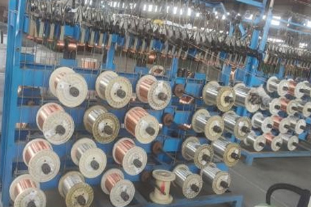
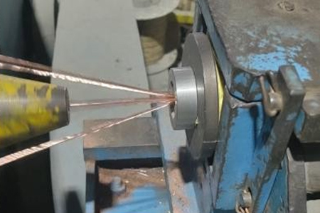
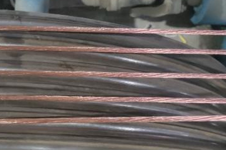
Phase Conductors: Start with finely stranded, tinned, soft-annealed copper wire. Extrude a semi-conducting layer over the conductor to act as a conductor shield and ensure smooth electrical fields.
Primary Insulation: Extrude a layer of Ethylene Propylene Rubber (EPR) over the semi-conducting layer. An additional semi-conducting EPR layer is then extruded over the insulation as a strippable insulation shield.
Ground & Ground Check Conductors: Prepare uninsulated flexible tinned copper ground wires and a ground check wire. The ground check wire must be extruded with high-strength, colored polypropylene insulation (typically yellow)
Secondly, Shielding & Core Assembly
Braid Shielding: Apply a composite tinned copper and color-coded textile/nylon braid (Black, Blue, Red for phase identification) over each of the insulated phase conductors to act as an individual electrostatic shield.
Cabling (Twisting): Lay up the three shielded phase conductors, two uninsulated ground conductors, and the yellow ground check conductor together with suitable rubber fillers to achieve a perfectly circular cross-section.
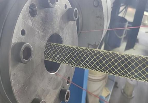
Bedding & Reinforcement: Wrap the cabled core with a single-faced rubber-filled binder tape and apply a reinforcing twine (reinforcing braid) to provide mechanical strength.
Thirdly Jacketing(Inner Sheath and Ourter Sheath)
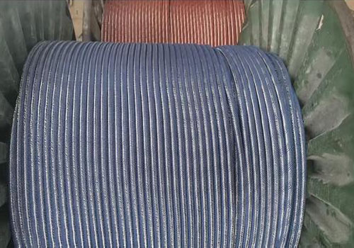
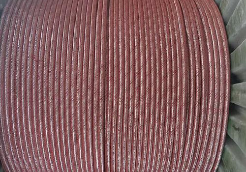
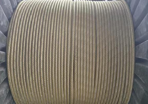
Inner & Outer Sheath: Extrude a heavy-duty thermosetting Chlorinated Polyethylene (CPE) compound over the assembly to form the inner jacket. For heavy-duty mining grades, apply a second outer CPE jacket.
Mold-Curing: For strict mining applications, the cable must pass through a continuous vulcanization (CV) or mold-curing process to cross-link the thermoset rubber and deliver extreme abrasion, oil, and chemical resistance.
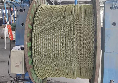
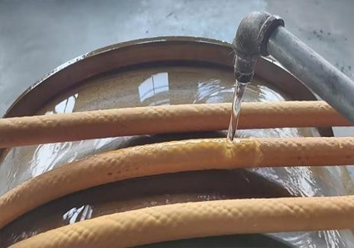
(N)TSCGEWÖU Cable Packaing Drum Material Design
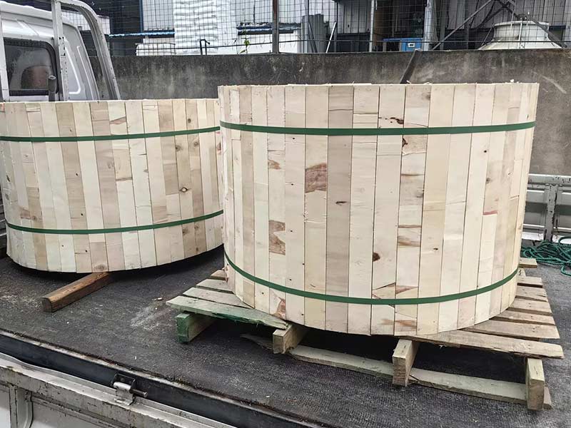
1. Packaging Reel Main Material: Pine/Poplar, Moisture Content 12–18% (Crack and Mildew Prevention)
2. Reel Body: Multi-layered solid wood plywood or hardwood splicing, crack-free and insect-free
3. Cable Reel Side Panels: Solid wood or multi-layered board, rounded edges R10–R15 (Cable Cut Prevention)
4. Reinforcement Layer: Side panels are bolted to the body with wooden dowels, plus 4–6 radial reinforcing ribs
5. Reel Surface: Clear varnish/waterproof paint, moisture-proof, antibacterial, and termite-proof
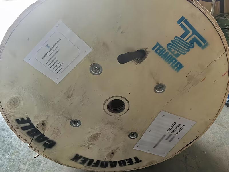
6. Cable Reel Printing Content: Manufacturer, cable specifications, length, etc
Request this cable.
Send the core configuration, length and application details.
Quality Assurance
Testing at every stage in our own workshop and laboratory, from incoming copper to the packed drum.
Raw Material Inspection
Every batch of copper rod, rubber compound and reinforcing material is checked before it reaches the line.
- Copper: conductor resistance, elongation and surface condition on incoming rod and drawn wire
- EPR, CPE, PUR and silicone compounds: hardness, tensile strength, elongation and ageing samples from each mix
- Suppliers and batch numbers are recorded so every drum can be traced back to its materials
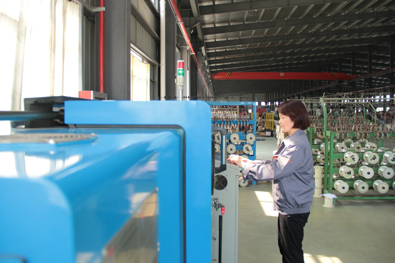
Manufacturing Process Control
Stranding, insulation extrusion, core assembly and sheathing run under recorded process parameters.
- Class 5/6 stranding with lay length and tension monitored for trailing and reeling flexibility
- Continuous-vulcanisation extrusion with wall thickness and spark tests logged on every length
- Operators sign off each stage before the cable moves to the next machine
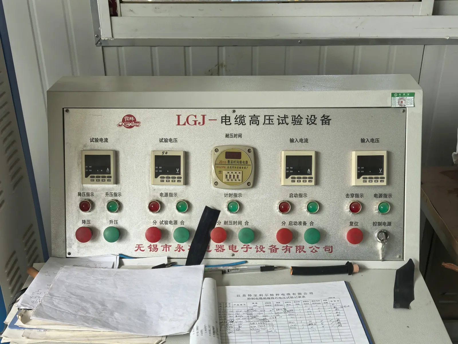
Electrical Testing
Finished lengths go through the routine tests required by the referenced VDE, ICEA, IEC or NEK standard.
- Conductor resistance and insulation resistance on every length
- Voltage withstand (3.5 kV and higher) and partial-discharge measurement in the shielded HV laboratory
- Screen and pilot-core continuity checks for mining and reeling constructions
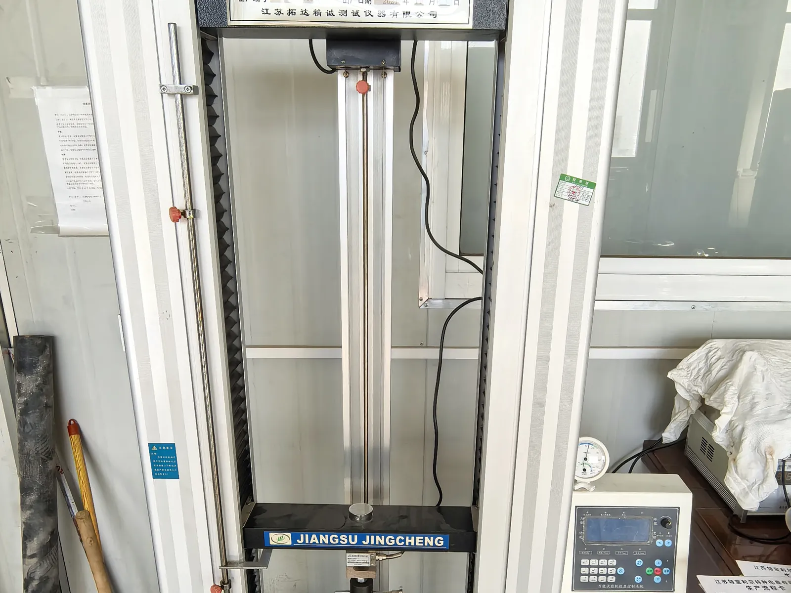
Mechanical and Ageing Tests
Samples from production are tested for the duty a mining, crane or submersible cable will actually see.
- Tensile strength and elongation of insulation and sheath before and after ageing
- Hot-set, ozone, oil-immersion and low-temperature bending tests
- Constant-temperature water bath for insulation resistance of submersible constructions
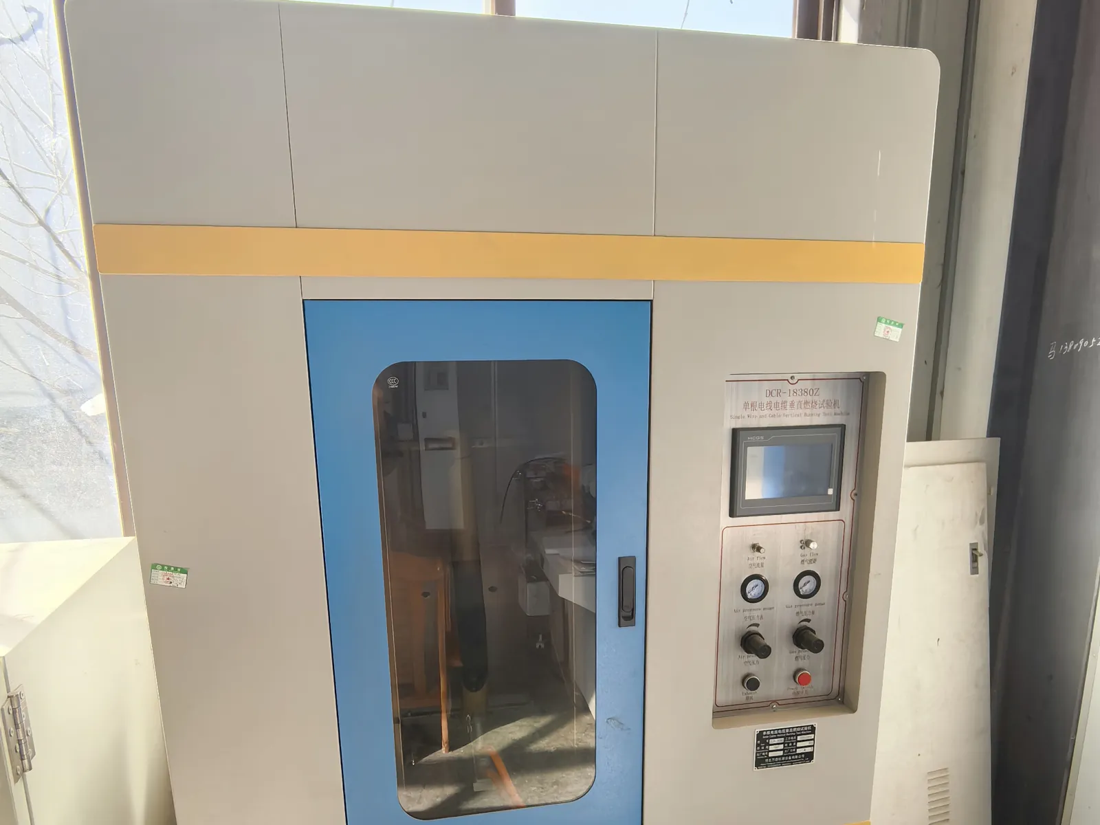
Flame Test and Final Inspection
Before packing, the cable is checked against the order and the flame-performance requirement of its standard.
- Single-cable vertical flame test to IEC 60332-1-2 where specified
- Metre marking, printing, drum length and appearance inspection
- Test report and packing list issued with every shipment
Related products
-
NTSCGECEWOU (N)TSCGECEWÖU Submersible ABT FO Mining Cable
-
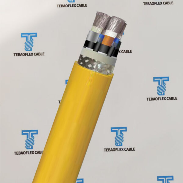
Heavy-Duty NSSHCGEÖU(Z) Reinforced Version Mining Cable
-
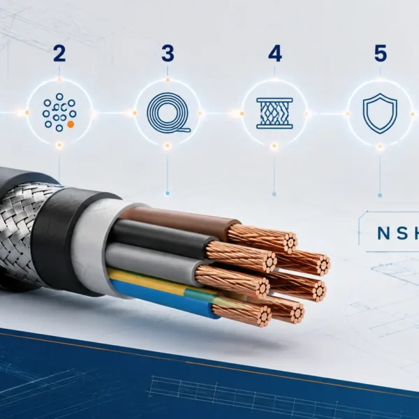
Olflex SMK NSHTOU J Rubber Crane Reeling Cable
-
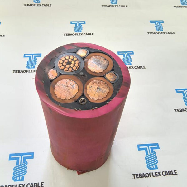
MV Motor RTS (N)TSCGEWTOEUS OFE Reeling Cable 3×70 + 3×35/3 + (20×2.5)C + 24FO (9/125)
-
NTSCGECWOEU Coal Cutter Cable VDE 0250 Mining Cable
-

1kV NSHTOEU Scoops LHDs Underground Mining Reeling Cable
-
3.6-30kV R-(N)TSCGEWÖU for open-cast mines cable
-
(N)3GHSSHCH LSZH Tunnelling & Underground Mining Cable
Need Pricing for This Cable?
Tell us the length, cores, cross-section and delivery country and we will reply with a quotation and datasheet.