

YKGYFoyn Steel Wire Armored Mining Cable | 0.6/1 & 3.6/6 kV
PVC mining power cable with round galvanized steel wire armor for shafts and inclined routes up to 90°. Choose 0.6/1 kV with 10-120 mm² power conductors or 3.6/6 kV with a copper tape screen and 10-185 mm² power conductors.
Overview
YKGYFoyn mining cable is a PVC-insulated copper power cable with round galvanized steel wire armor. The range includes 0.6/1 kV equipment-supply and 3.6/6 kV mine-distribution versions, both suitable for shafts and inclined excavations up to 90 degrees. Each voltage version has its own conductor construction, sheath color, dimensions and electrical data.
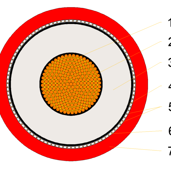
The low-voltage version combines class 1 or class 2 copper conductors with a yellow PVC outer sheath. The medium-voltage version uses compacted class 2 copper conductors, a common copper tape screen, a separating layer and a red PVC outer sheath. These are distinct constructions within the YKGYFoyn family, so specify the voltage as well as the full cable configuration.
Eight low-voltage and ten medium-voltage configurations are listed below. The power-conductor range is 10-120 mm² at 0.6/1 kV and 10-185 mm² at 3.6/6 kV. Use the corresponding table when reviewing a replacement, because a shared model name or conductor size does not establish the same diameter, weight or termination requirements.
Selection should begin with the supply voltage, mine environment and route. The technical sections explain the construction differences and the checks needed for shaft support, bend space and electrical sizing. Explore the wider mining cable range, or use the YKGYFoyn PDF datasheet when preparing the project cable schedule.
Construction
Choose the YKGYFoyn voltage construction before specifying cable entries or terminations. Both versions use round galvanized steel wire armor; the 3.6/6 kV version adds a copper tape screen and a separating layer.
| Element | 0.6/1 kV | 3.6/6 kV |
|---|---|---|
| Conductors | Solid copper class 1 or stranded copper class 2 | Compacted stranded copper class 2 |
| Insulation | Special PVC | Special PVC |
| Core identification | Power: natural, red and blue; protective: natural | Natural cores numbered 1, 2 and 3 |
| Core assembly | Power cores and protective elements | Power cores around a PVC liner |
| Filler / inner sheath | PVC or rubber / PVC | PVC or rubber / PVC |
| Screen and separation | Power-core and protective-element construction | Copper tape screen; PVC separating sheath or tape |
| Armor | Round galvanized steel wires | Round galvanized steel wires |
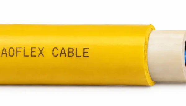
| Outer sheath | Yellow special flame-retardant PVC | Red special flame-retardant PVC |
| Oxygen index | >29 | >29 |
Keep the voltage construction on the order
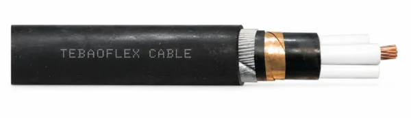
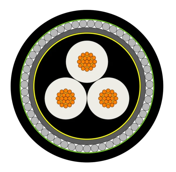
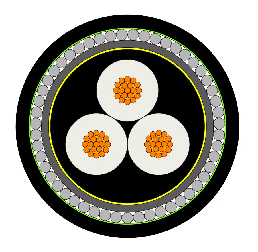
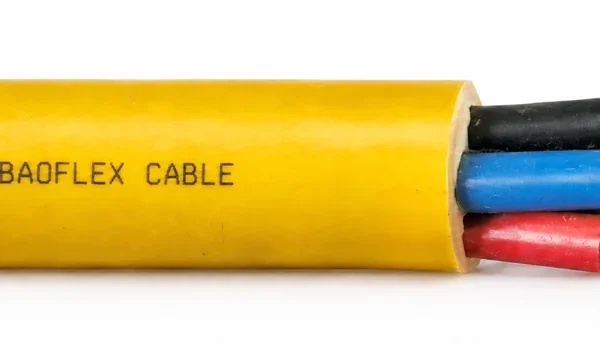
A copper tape screen is part of the medium-voltage construction. Use the matching drawing for stripping, bonding and gland selection. The low-voltage protective arrangement must be checked for the chosen configuration instead of being inferred from the three-power-core illustration.
For the 3.6/6 kV version, the filler and inner sheath may form one component when their materials match. Confirm the final layer arrangement with the termination details.
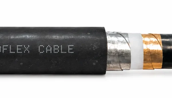
Match the illustration to the voltage construction
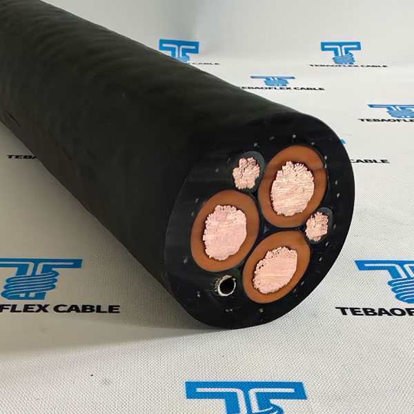
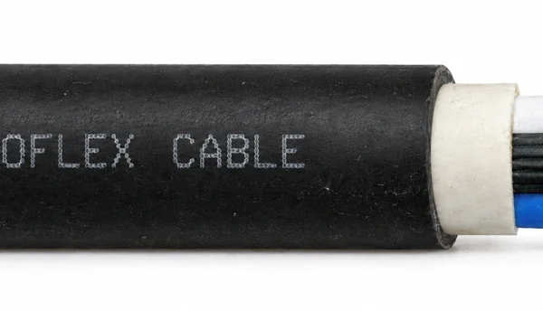
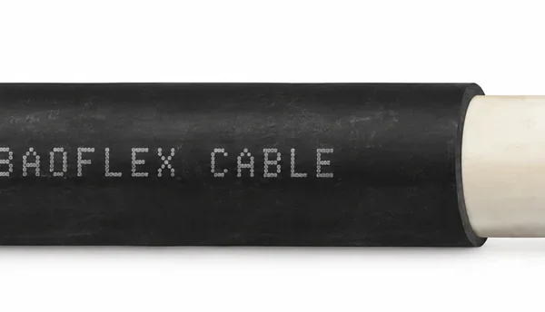
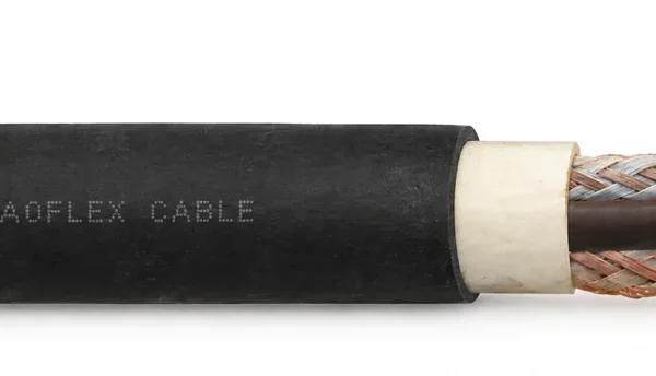
The product cutaway illustrates the medium-voltage construction with a copper tape screen and uses black outer-sheath coloring. Specify yellow PVC for the 0.6/1 kV version or red PVC for the 3.6/6 kV version. Confirm the protective-element arrangement and termination drawing for the selected voltage.
Applications
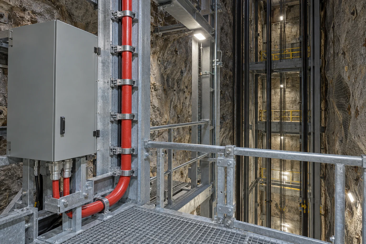
YKGYFoyn supplies mining electrical equipment and mine power-distribution routes. Both voltage versions are suitable for shafts and excavations inclined up to 90°.
0.6/1 kV equipment supply
Use the low-voltage construction for open-pit and underground equipment in methane-free seams, areas without explosion hazards and excavations classified as class A for coal-dust explosion hazard. Match the project's mine-area classification before selecting the cable.
3.6/6 kV power distribution
The medium-voltage construction carries power through mine distribution routes. Specify the copper tape screen, armor and termination arrangement together. Before ordering, ask our engineers to confirm the site's area classification and required approval documentation.
Design the shaft support arrangement
The 90° route allowance does not determine the support spacing or the length that may hang between fixings. Review cable weight, shaft depth, clamp design and installation loads as a complete route. Allow at least 10 times the cable outside diameter at bends. Install the 0.6/1 kV version at or above -5°C.
Specifications
| Parameter | 0.6/1 kV | 3.6/6 kV |
|---|---|---|
| Operating voltage | 0.6/1 kV | 3.6/6 kV |
| Test voltage | 3.5 kV | 11 kV |
| Operating temperature | -30°C to +70°C | -30°C to +70°C |
| Minimum bending radius | 10 × OD | 10 × OD |
| Shaft / excavation inclination | Up to 90° | Up to 90° |
Minimum installation temperature for the 0.6/1 kV version: -5°C. OD means cable outside diameter. Keep voltage, model and the complete configuration together on the purchase specification.
0.6/1 kV dimensions and electrical data
| Model and cable construction (mm²) | Power section (mm²) | Maximum outside diameter (mm) | Weight (kg/km) |
|---|---|---|---|
| YKGYFoyn 3x10/6 | 10 | 25.9 | 1600 |
| YKGYFoyn 3x16/16 | 16 | 28.4 | 2040 |
| YKGYFoyn 3x25/16 | 25 | 32.6 | 2600 |
| YKGYFoyn 3x35/16 | 35 | 34.3 | 2990 |
| YKGYFoyn 3x50/16 | 50 | 37.9 | 3680 |
| YKGYFoyn 3x70/25 | 70 | 43.2 | 4780 |
| YKGYFoyn 3x95/25 | 95 | 48.6 | 5950 |
| YKGYFoyn 3x120/35 | 120 | 52.9 | 7140 |
| Power section (mm²) | Resistance (Ω/km) | Inductivity (mH/km) | Reactance (Ω/km) | Long-term current (A) | 1 s short circuit (kA) |
|---|---|---|---|---|---|
| 10 | 1.83 | 0.31 | 0.098 | 64 | 1.15 |
| 16 | 1.15 | 0.30 | 0.092 | 86 | 1.84 |
| 25 | 0.727 | 0.30 | 0.092 | 113 | 2.88 |
| 35 | 0.524 | 0.29 | 0.090 | 139 | 4.03 |
| 50 | 0.387 | 0.28 | 0.088 | 173 | 5.75 |
| 70 | 0.268 | 0.26 | 0.085 | 212 | 8.05 |
| 95 | 0.193 | 0.26 | 0.084 | 257 | 10.93 |
| 120 | 0.153 | 0.26 | 0.083 | 294 | 13.80 |
The low-voltage short-circuit capacity is for 1 s at the maximum long-term conductor temperature.
3.6/6 kV dimensions and electrical data
| Model and cable construction (mm²) | Power section (mm²) | Calculated outside diameter (mm) | Weight (kg/km) |
|---|---|---|---|
| YKGYFoyn 3x10/10 | 10 | 46.8 | 4715 |
| YKGYFoyn 3x16/10 | 16 | 49.6 | 5290 |
| YKGYFoyn 3x25/14 | 25 | 52.5 | 5963 |
| YKGYFoyn 3x35/16 | 35 | 53.9 | 6460 |
| YKGYFoyn 3x50/18 | 50 | 59.2 | 8315 |
| YKGYFoyn 3x70/18 | 70 | 64.5 | 9753 |
| YKGYFoyn 3x95/20 | 95 | 68.8 | 11178 |
| YKGYFoyn 3x120/22 | 120 | 71.3 | 12670 |
| YKGYFoyn 3x150/24 | 150 | 75.5 | 14455 |
| YKGYFoyn 3x185/27 | 185 | 84.5 | 18462 |
| Power section (mm²) | Resistance (Ω/km) | Inductivity (mH/km) | Reactance (Ω/km) |
|---|---|---|---|
| 10 | 1.83 | 0.400 | 0.126 |
| 16 | 1.15 | 0.372 | 0.117 |
| 25 | 0.727 | 0.349 | 0.110 |
| 35 | 0.524 | 0.338 | 0.106 |
| 50 | 0.387 | 0.317 | 0.100 |
| 70 | 0.268 | 0.299 | 0.094 |
| 95 | 0.193 | 0.286 | 0.090 |
| 120 | 0.153 | 0.278 | 0.087 |
| 150 | 0.124 | 0.268 | 0.084 |
| 185 | 0.0991 | 0.262 | 0.082 |
| Power section (mm²) | Earth capacitance (µF/km) | Earth SC (A/km) | Short circuit (kA) | Current (A) |
|---|---|---|---|---|
| 10 | 0.11 | 0.35 | 1.15 | 68 |
| 16 | 0.11 | 0.37 | 1.84 | 87 |
| 25 | 0.12 | 0.40 | 2.88 | 113 |
| 35 | 0.13 | 0.41 | 4.03 | 137 |
| 50 | 0.13 | 0.43 | 5.75 | 164 |
| 70 | 0.14 | 0.45 | 8.05 | 202 |
| 95 | 0.15 | 0.47 | 10.93 | 245 |
| 120 | 0.15 | 0.49 | 13.8 | 281 |
| 150 | 0.15 | 0.50 | 17.25 | 319 |
| 185 | 0.16 | 0.51 | 21.28 | 369 |
Earth-data key: Earth capacitance means to-earth capacitance. Earth SC means to-earth short-circuit current, expressed in A/km; it is separate from the short-circuit value in kA. Before ordering, confirm the fault duration, installation arrangement, ambient temperature and load conditions for the protection and conductor-sizing calculations.
Standards
| Reference | 0.6/1 kV | 3.6/6 kV |
|---|---|---|
| PN-EN 60332-1 | Single-cable flame-propagation reference | Single-cable flame-propagation reference |
| PN-EN 60332-3-24 / IEC 60332-3 | Bunched-cable flame-propagation references | Bunched-cable flame-propagation references |
| Oxygen index | Outer sheath >29 | Outer sheath >29 |
| Test voltage | 3.5 kV | 11 kV |
Specify the required standard editions, inspection records and project acceptance documents with the voltage and full cable designation. Flame-propagation references and electrical test voltages describe different checks.
Request Quote
Send the YKGYFoyn configuration, required voltage, length and quantity, installation duty, equipment connection details and sheath color. Include the protective-core, screen or armor requirements that apply to the selected construction, together with inspection requirements.
You can also use our technical contact form.
Quality Assurance
Testing at every stage in our own workshop and laboratory, from incoming copper to the packed drum.
Raw Material Inspection
Every batch of copper rod, rubber compound and reinforcing material is checked before it reaches the line.
- Copper: conductor resistance, elongation and surface condition on incoming rod and drawn wire
- EPR, CPE, PUR and silicone compounds: hardness, tensile strength, elongation and ageing samples from each mix
- Suppliers and batch numbers are recorded so every drum can be traced back to its materials
Manufacturing Process Control
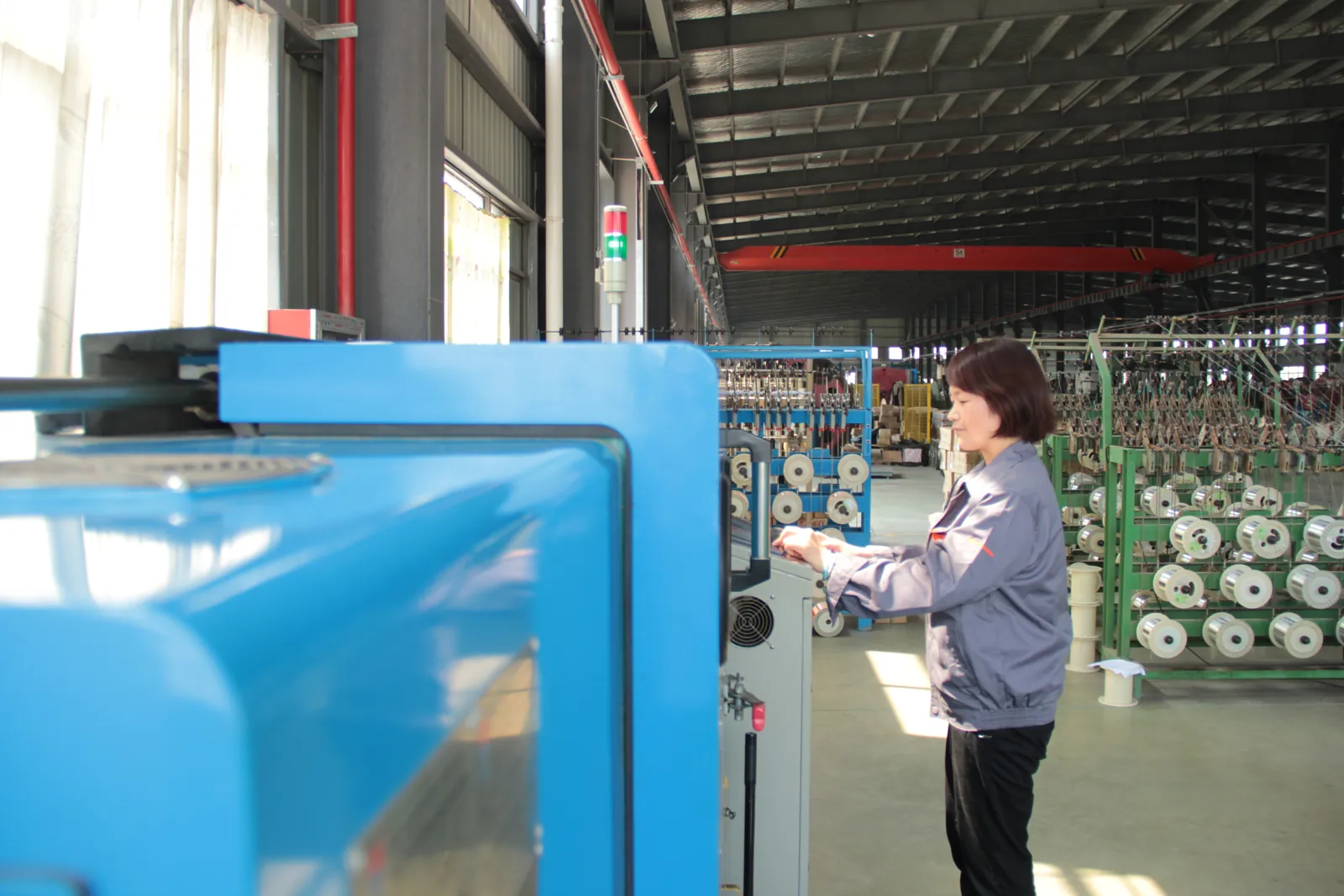
Stranding, insulation extrusion, core assembly and sheathing run under recorded process parameters.
- Class 5/6 stranding with lay length and tension monitored for trailing and reeling flexibility
- Continuous-vulcanisation extrusion with wall thickness and spark tests logged on every length
- Operators sign off each stage before the cable moves to the next machine
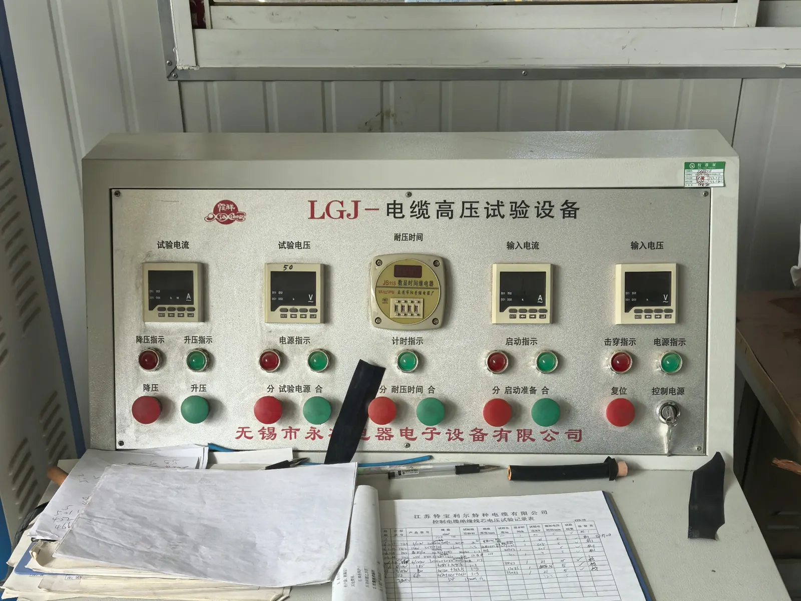
Electrical Testing
Finished lengths go through the routine tests required by the referenced VDE, ICEA, IEC or NEK standard.
- Conductor resistance and insulation resistance on every length
- Voltage withstand (3.5 kV and higher) and partial-discharge measurement in the shielded HV laboratory
- Screen and pilot-core continuity checks for mining and reeling constructions
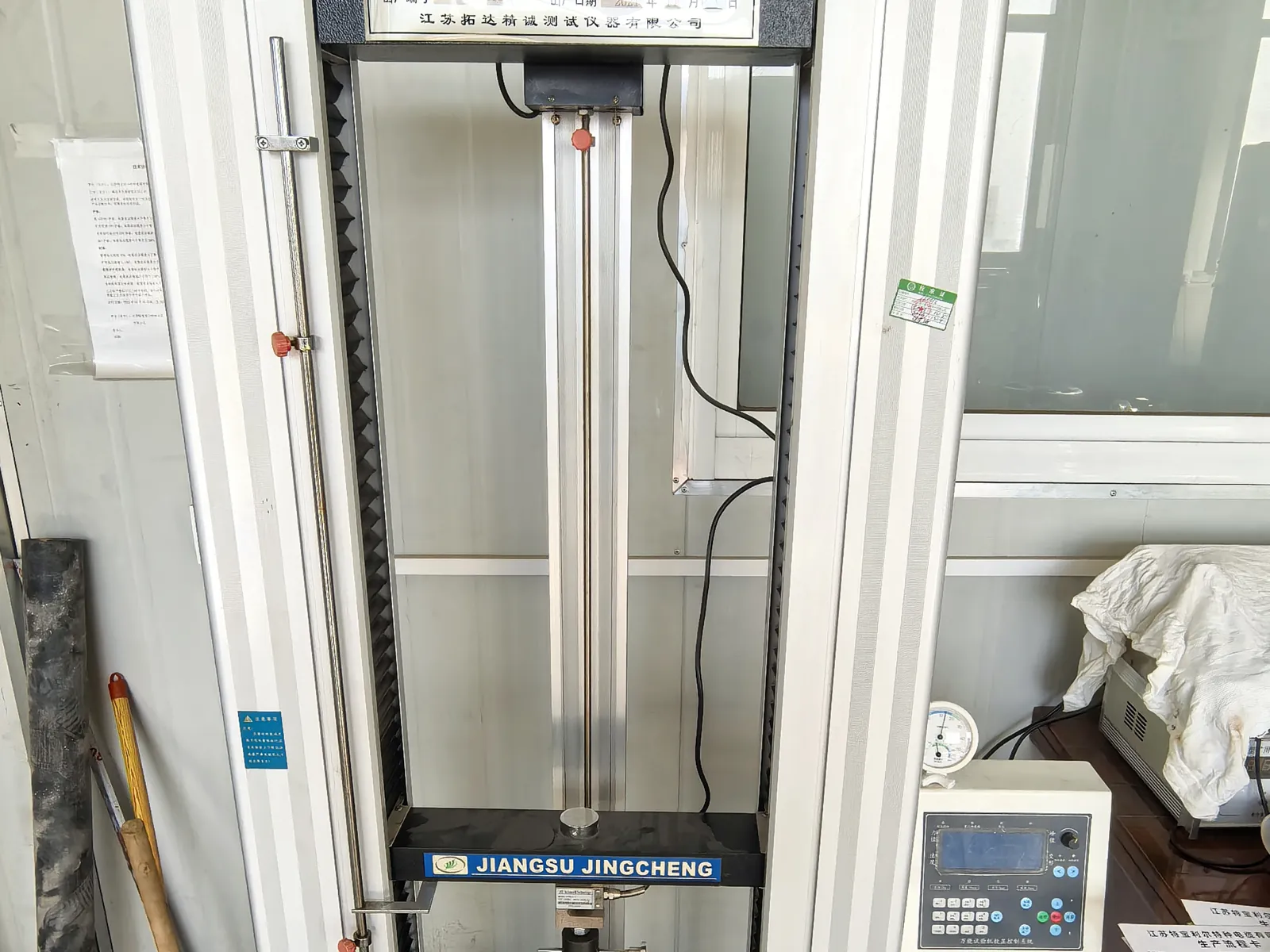
Mechanical and Ageing Tests
Samples from production are tested for the duty a mining, crane or submersible cable will actually see.
- Tensile strength and elongation of insulation and sheath before and after ageing
- Hot-set, ozone, oil-immersion and low-temperature bending tests
- Constant-temperature water bath for insulation resistance of submersible constructions
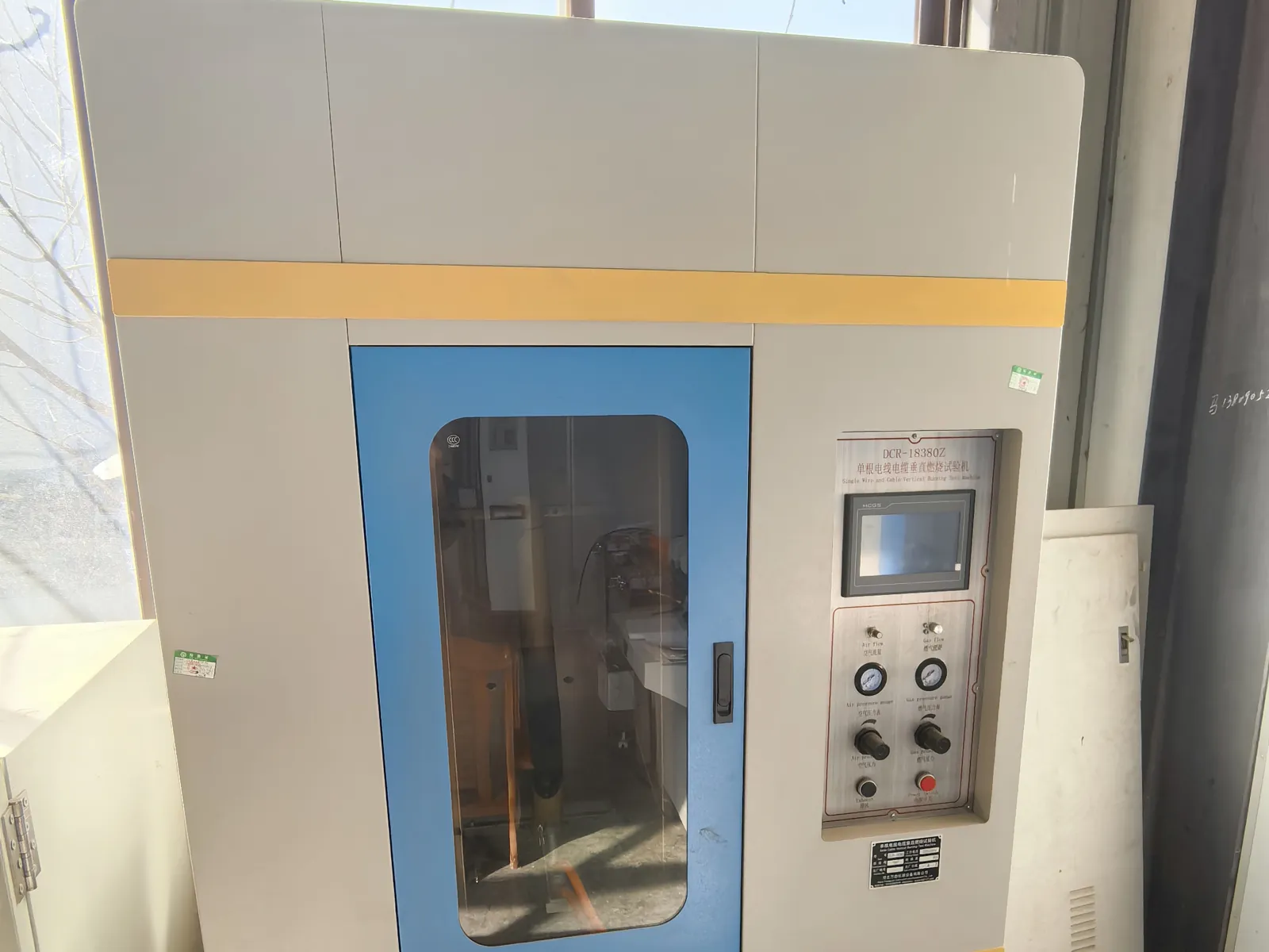
Flame Test and Final Inspection
Before packing, the cable is checked against the order and the flame-performance requirement of its standard.
- Single-cable vertical flame test to IEC 60332-1-2 where specified
- Metre marking, printing, drum length and appearance inspection
- Test report and packing list issued with every shipment
You may also like…
Related products
Need Pricing for This Cable?
Tell us the length, cores, cross-section and delivery country and we will reply with a quotation and datasheet.