
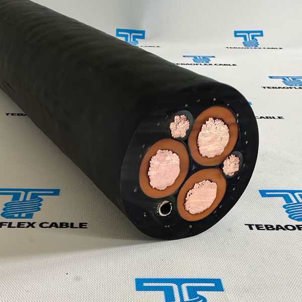
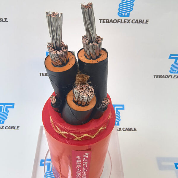
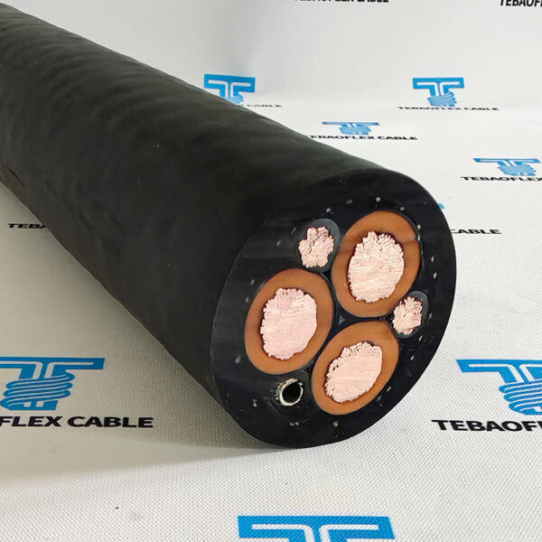
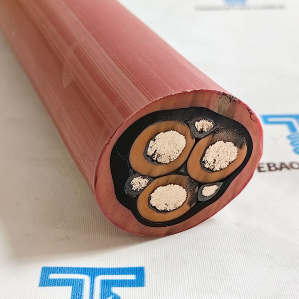
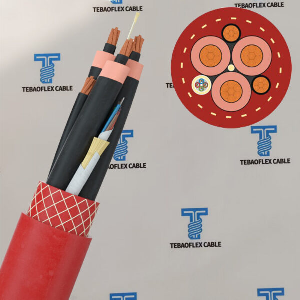
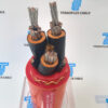
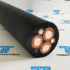
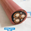
F-(N)TSCGEWÖU LWL TBM Reeling Mine Cable
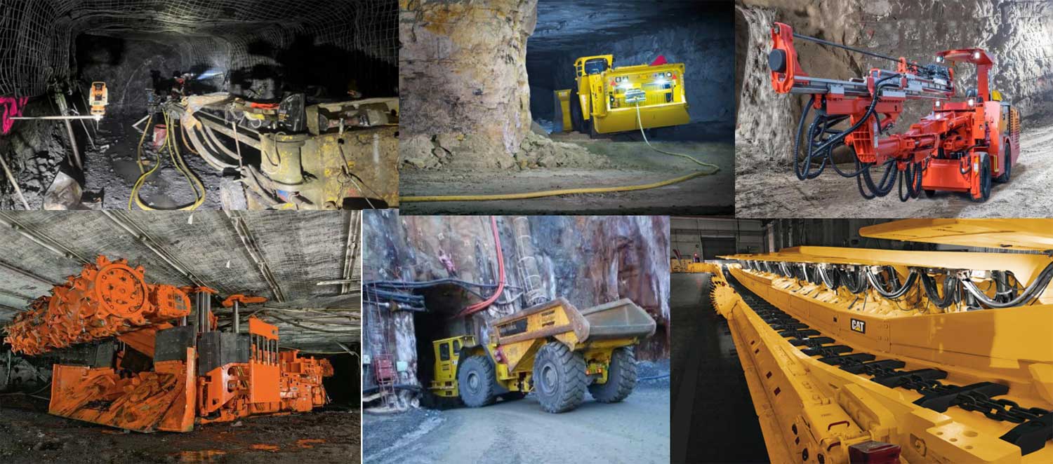
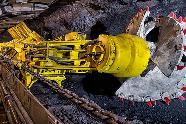
(N)TSCGEWOU-TBM LWL Cable are suitable for reeling power supply cables for TBM’s machines and in underground mines for tunnel constructions.
- Voltage3.6/6kV – 12/20kV
- StandardDIN VDE 0250-813
- ConductorFlexible red copper, Class 5
- InsulationRubber EPR compound
- Outer sheathRED PCP compound
- Size range3×25 + 3×25/3 – 3×300 + 3×150/3
- Outer diameter38,2 – 89,8 mm
- Cable weight (approx.)2315 – 16080 kg/km
(N)TSCGEWOU-TBM LWL Cable are suitable for reeling power supply cables for TBM’s machines and in underground mines for tunnel constructions.
F-(N)TSCGEWÖU LWL Reeling Mine Cable are especially for mobile facilities such as fast running container cranes, crane facilities, mobile heavy equipment and diggers. Suitable for dry, humid and wet rooms and for outdoor use.
The Reeling Cable Feature:
- Suitable for Conveyor Belts
- Very flexible
- Oil-resistant, waterproof, tear-resistant.
What’s F-(N)TSCGEWÖU?
F-(N)TSCGEWÖU is a medium-voltage flexible mining power cable for fixed installation, developed in accordance with DIN VDE 0250-813 for demanding mining, tunnelling, and bulk material handling applications.
Unlike the standard (N)TSCGEWÖU trailing cable, which is designed for continuous cable reeling and mobile equipment, the F-(N)TSCGEWÖU version is optimized for fixed or semi-fixed power distribution where high electrical reliability is required but continuous trailing movement is not.
The prefix “F” stands for Fixed Installation, indicating that the cable is intended for stationary installation alongside conveyor systems, transfer stations, shiftable mining equipment, substations, cable booms, and submersible pump installations. Although the cable remains highly flexible, its primary purpose is to provide a durable medium-voltage power connection rather than repeated trailing or high-speed reeling.
F-(N)TSCGEWÖU maintains the same premium electrical construction found in the standard cable, including:
- Class 5 flexible tinned copper conductors
- Semi-conductive conductor and insulation screens
- High-performance EPR insulation
- Split earth conductors
- Heavy-duty PCP rubber outer sheath
- Excellent resistance to moisture, ozone, oil, UV radiation, and mechanical impact
Application & Features
Selection overview
Which Types of Cable Should You Choose?
- Choose F-(N)TSCGEWÖU if your application requires a flexible medium-voltage cable installed in a fixed position with only occasional movement.
- Choose (N)TSCGEWÖU if your equipment is continuously moving and the cable must withstand repeated bending, torsion, and high-speed reeling throughout its service life.
- Selecting the appropriate cable not only improves operational reliability but also reduces maintenance costs and extends cable service life.
Specifications
Technical data
(N)TSCGEWOU TBM Reeling Mine Cable Technical
Temperature range
- Fixed installation: – 40°C + 80°C
- Flexible installation: – 25°C + 60°C
- Test voltage: 11000 V to 43000 V, acc. to DIN VDE 0250, part 813
Max. permessible temperature
- on conductor: + 90°C Max. permessible temperature
- On short-circuit: + 250°C
- Max. permessible operating voltage in A.C.systems: UoU 4.2/7.2 kV to 20.8/36 kV
- Max. permessible operating voltage in D.C. systems: UoU 5.4/10.8 kV to 27/54 kV
- Tensile load: up to 20 N/mm2 Torsional stresses: ± 100°/m
- Max. speed: 100 m/min Oil resistant: acc. to DIN VDE 0473 part 811-2-1 part 10
- Fire resistant: acc. to DIN VDE 0482 EN IEC 60332-1-2
- Weather resistance: outdoor use, resistant to moisture ozone and UV rays
F-(N)TSCGEWÖU TBM Reeling Cable Technical Information
3,6/6 (7,2) kV F-(N)TSCGEWÖU Reeling Cable
| No. of cores | Outer-Ø ca. mm. | Copper weight | Cable weight approx. | Tensile strength | AWG |
|---|---|---|---|---|---|
| x cross-section n x mm2 | ± 10% | kg/km | kg/km | N | no.*) |
| (N)TSCGEWOU 3×25 + 3×25/3 | 38,2 | 960 | 2315 | 1125 | 4 |
| (N)TSCGEWOU 3×25 + 3×50/3 | 42,1 | 1200 | 2875 | 1125 | 4 |
| (N)TSCGEWOU 3×35 + 3×25/3 | 42 | 1248 | 2868 | 1575 | 2 |
| (N)TSCGEWOU 3×35 + 3×50/3 | 43,8 | 1488 | 3230 | 1575 | 2 |
| (N)TSCGEWOU 3×50 + 3×25/3 | 45,3 | 1680 | 3515 | 2250 | 1 |
| (N)TSCGEWOU 3×50 + 3×50/3 | 45,3 | 1920 | 3655 | 2250 | 1 |
| (N)TSCGEWOU 3×70 + 3×25/3 | 48,5 | 2256 | 4368 | 3150 | 2/0 |
| (N)TSCGEWOU 3×70 + 3×50/3 | 51,7 | 2496 | 5018 | 3150 | 2/0 |
| (N)TSCGEWOU 3×95 + 3×50/3 | 54,6 | 3216 | 5547 | 4275 | 3/0 |
| (N)TSCGEWOU 3×120 + 3×70/3 | 57,9 | 4128 | 6680 | 5400 | 4/0 |
| (N)TSCGEWOU 3×150 + 3×70/3 | 63 | 4992 | 8015 | 6750 | 250 MCM |
| (N)TSCGEWOU 3×185 + 3×95/3 | 66 | 6240 | 9310 | 8325 | 350 MCM |
| (N)TSCGEWOU 3×240 + 3×120/3 | 74,1 | 8064 | 11966 | 10800 | 450 MCM |
| (N)TSCGEWOU 3×300 + 3×150/3 | 79,3 | 10080 | 14245 | 13500 | 550 MCM |
6/10 (12) kV F-(N)TSCGEWÖU Reeling Cable
| No. of cores | Outer-Ø ca. mm. | Copper weight | Cable weight approx. | Tensile strength | AWG |
|---|---|---|---|---|---|
| x cross-section n x mm2 | ± 10% | kg/km | kg/km | N | no.*) |
| F-(N)TSCGEWÖU 3×25 + 3×25/3 | 40,5 | 960 | 2510 | 1125 | 4 |
| F-(N)TSCGEWÖU 3×25 + 3×50/3 | 42,9 | 1200 | 2915 | 1125 | 4 |
| F-(N)TSCGEWÖU 3×35 + 3×25/3 | 43,3 | 1248 | 2987 | 1575 | 2 |
| F-(N)TSCGEWÖU 3×35 + 3×50/3 | 45,1 | 1488 | 3340 | 1575 | 2 |
| F-(N)TSCGEWÖU 3×50 + 3×25/3 | 46,6 | 1680 | 3635 | 2250 | 1 |
| F-(N)TSCGEWÖU 3×50 + 3×50/3 | 46,6 | 1920 | 3740 | 2250 | 1 |
| F-(N)TSCGEWÖU 3×70 + 3×25/3 | 49,8 | 2256 | 4510 | 3150 | 2/0 |
| F-(N)TSCGEWÖU 3×70 + 3×50/3 | 49,8 | 2496 | 4715 | 3150 | 2/0 |
| F-(N)TSCGEWÖU 3×95 + 3×50/3 | 55,5 | 3216 | 5721 | 4275 | 3/0 |
| F-(N)TSCGEWÖU 3×120 + 3×70/3 | 59,2 | 4128 | 6869 | 5400 | 4/0 |
| F-(N)TSCGEWÖU 3×150 + 3×70/3 | 64,3 | 4992 | 8201 | 6750 | 250 MCM |
| F-(N)TSCGEWÖU 3×185 + 3×95/3 | 67,3 | 6240 | 9515 | 8325 | 350 MCM |
| F-(N)TSCGEWÖU 3×240 + 3×120/3 | 75,4 | 8064 | 12180 | 10800 | 450 MCM |
| F-(N)TSCGEWÖU 3×300 + 3×150/3 | 80,6 | 10080 | 14515 | 13500 | 550 MCM |
8,7/15 (18) kV F-(N)TSCGEWÖU Reeling Cable
| No. of cores | Outer-Ø ca. mm. | Copper weight | Cable weight approx. | Tensile strength | AWG |
|---|---|---|---|---|---|
| x cross-section n x mm2 | ± 10% | kg/km | kg/km | N | no.*) |
| (N)TSCGEWÖU 3×25 + 3×25/3 | 44 | 960 | 2857 | 1125 | 4 |
| (N)TSCGEWÖU 3×25 + 3×50/3 | 45,7 | 1200 | 3218 | 1125 | 4 |
| (N)TSCGEWÖU 3×35 + 3×25/3 | 46,8 | 1248 | 3348 | 1575 | 2 |
| (N)TSCGEWÖU 3×35 + 3×50/3 | 46,8 | 1488 | 3466 | 1575 | 2 |
| (N)TSCGEWÖU 3×50 + 3×25/3 | 51,4 | 1680 | 4188 | 2250 | 1 |
| (N)TSCGEWÖU 3×50 + 3×50/3 | 51,4 | 1920 | 4312 | 2250 | 1 |
| (N)TSCGEWÖU 3×70 + 3×25/3 | 54,7 | 2256 | 5100 | 3150 | 2/0 |
| (N)TSCGEWÖU 3×70 + 3×50/3 | 54,7 | 2496 | 5320 | 3150 | 2/0 |
| (N)TSCGEWÖU 3×95 + 3×50/3 | 59 | 3216 | 6175 | 4275 | 3/0 |
| (N)TSCGEWÖU 3×120 + 3×70/3 | 64,1 | 4128 | 7540 | 5400 | 4/0 |
| (N)TSCGEWÖU 3×150 + 3×70/3 | 67,7 | 4992 | 8715 | 6750 | 250 MCM |
| (N)TSCGEWÖU 3×185 + 3×95/3 | 70,7 | 6240 | 10035 | 8325 | 350 MCM |
| (N)TSCGEWÖU 3×240 + 3×120/3 | 78,8 | 8064 | 12738 | 10800 | 450 MCM |
| (N)TSCGEWÖU 3×300 + 3×150/3 | 84 | 10080 | 15118 | 13500 | 550 MCM |
12/20 (24) kV F-(N)TSCGEWÖU Reeling Cable
| No. of cores | Outer-Ø ca. mm. | Copper weight | Cable weight approx. | Tensile strength | AWG |
|---|---|---|---|---|---|
| x cross-section n x mm2 | ± 10% | kg/km | kg/km | N | no.*) |
| 3×25 + 3×25/3 | 47 | 960 | 3140 | 1125 | 4 |
| 3×25 + 3×50/3 | 48,7 | 1200 | 3312 | 1125 | 4 |
| 3×35 + 3×25/3 | 49,8 | 1248 | 3672 | 1575 | 2 |
| 3×35 + 3×50/3 | 53 | 1488 | 3823 | 1575 | 2 |
| 3×50 + 3×25/3 | 54,5 | 1680 | 4530 | 2250 | 1 |
| 3×50 + 3×50/3 | 54,5 | 1920 | 4675 | 2250 | 1 |
| 3×70 + 3×25/3 | 57,7 | 2256 | 5466 | 3150 | 2/0 |
| 3×70 + 3×50/3 | 60 | 2496 | 5701 | 3150 | 2/0 |
| 3×95 + 3×50/3 | 63,4 | 3216 | 6780 | 4275 | 3/0 |
| 3×120 + 3×70/3 | 67,1 | 4128 | 7985 | 5400 | 4/0 |
| 3×150 + 3×70/3 | 70,7 | 4992 | 9180 | 6750 | 250 MCM |
| 3×185 + 3×95/3 | 75,2 | 6240 | 10791 | 8325 | 350 MCM |
| 3×240 + 3×120/3 | 81,8 | 8064 | 13290 | 10800 | 450 MCM |
| 3×300 + 3×150/3 | 89,8 | 10080 | 16080 | 13500 | 550 MCM |
Standards & References
Applicable standards
(N)TSCGEWOU TBM Reeling Mine Cable International Standard
- constructionDIN VDE 0250-813
- General RequirementsDIN VDE 0250-1
- Guide UseDIN VDE 0298-3
- Electrical TestsDIN VDE 0472-501, 503, 508
- Non-Electrical TestsDIN VDE 0472-401. 402,602,303, 615
- Under Fire Condition TestsDIN VDE 0472-803, 804
- Flame RetardantVDE 0482-332-1-2,DIN EN 60332-1-2,IEC 60332-1
- Oil ResistantHD/EN/IEC 60811-2-1.,DIN VDE0473-811-2-1
Construction
Material and build-up
F-(N)TSCGEWÖU LWL TBM Construction
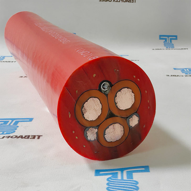
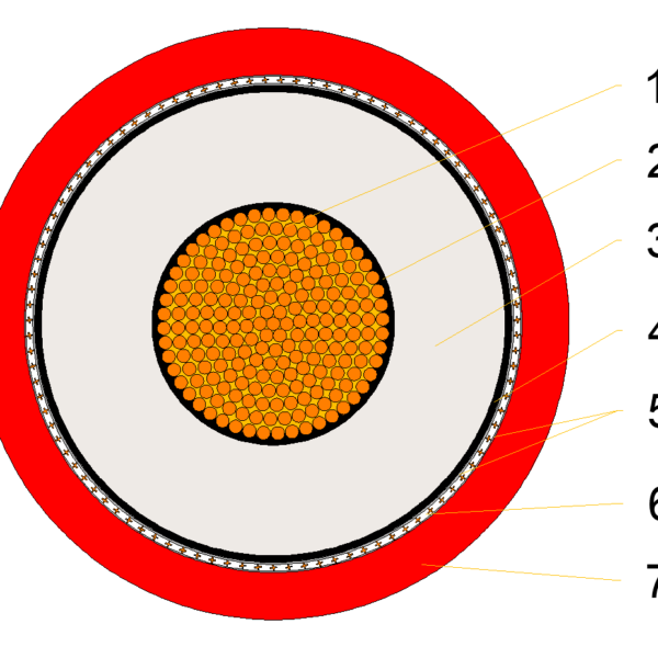
- Conductor: Flexible red copper conductor Class5. acc. to IEC 60228, DIN VDE 0295
- Conductor screen: semi-conducting compound
- Insulation: rubber EPR compound Core screen: semi-conducting compound
- Earth conductor: Flexible red copper conductor Cl. 5, acc to IEC 60228, DIN VDE 0295
- Option: rubber compound; FO: with jelly filled PETP tubes in an envelope of heat resistant compound
- Earth core screen: semi-conducting compound
- Cores color: POWER: natural color with black semi-contuctive compound
- Earth: black semi-contuctive compound
- Stranding: three main core placed with earth-conductor divided in three in the outer interstices
- Inner sheath: EPR compound
- Outer sheath: RED PCP compound(Red)
More Details
Comparison and references
Difference Between F-(N)TSCGEWÖU and (N)TSCGEWÖU
Although both cables are manufactured according to the same VDE mining cable standard and share similar electrical construction, they are designed for different operating conditions.
| Feature | F-(N)TSCGEWÖU | (N)TSCGEWÖU |
|---|---|---|
| Primary Purpose | Fixed installation | Trailing & reeling applications |
| Installation | Stationary or semi-fixed | Continuously moving equipment |
| Mechanical Stress | Medium | Very high |
| Torsional Stress | Low | High |
| Cable Reeling | Not recommended for continuous reeling | Specifically designed for continuous reeling |
| Typical Equipment | Conveyor systems, substations, pump stations | Draglines, electric shovels, bucket-wheel excavators, continuous miners |
| Cable Movement | Occasional | Continuous |
| Service Environment | Fixed mining infrastructure | Mobile mining machinery |
Precautions for using (N)TSCGEWöU Reeling Cable in TBM Equipment
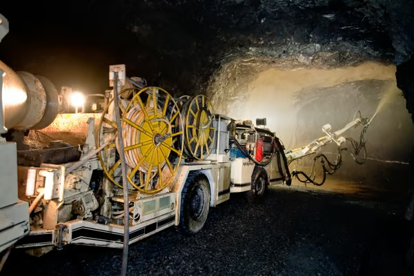
(N) TSCGEWöU is a commonly used medium voltage drum-type reeling cable for TBMs/tunnel boring machines. The key is to strictly control bending/torsion/tension, ensure proper protection and winding management, standardize joint connections and inspections, and adapt to the underground environment. Otherwise, core breakage, sheath cracking, shielding failure, and short circuits are likely to occur.
I. Core Parameter Limits (Must be observed)
- Rated Voltage: 3.6/6kV, 6/10kV, 8.7/15kV, 12/20kV
- Long-term Temperature: 90℃; Minimum -25℃ for mobile installations, -40℃ for fixed installations.
- Minimum Bending Radius: Fixed 6D, Mobile 10D (D = Cable Outer Diameter)
- Maximum Torsion: ±25°/m, excessive torsion is strictly prohibited.
- Maximum Tensile Force: ≤20–25kN (according to cross-section and manufacturer’s specifications)
II. Installation and Laying Precautions
1. Route and Bending
- o Avoid sharp angles and sharp bends throughout the installation; dynamic sections should have a radius ≥10D; use curved cable guides/pulleys at bends.
- o Allow 0.5–1m slack every 10m to prevent stretching; dragging, rolling, and pulling are strictly prohibited.
2. Fixing and Protection
- o Secure with dedicated clamps every 2–3m, adding wear-resistant rubber/nylon sliders at metal contact points.
- o Single-layer arrangement within the drum/drag chain, no cross-stacking; drum diameter ≥12D.
- o Wear prevention: Install protective grooves/guide frames inside the tunnel to avoid friction with tunnel segments and steel structures.
3. Joints and Terminals
- o High-voltage joints use cold-shrink/heat-shrink terminals, waterproof rating ≥IP68; shielding layer continuously grounded 360°.
- o Joints should be kept away from bending/stretching areas; joints must not pass over the drum.
Request this cable.
Send the core configuration, length and application details.
Quality Assurance
Testing at every stage in our own workshop and laboratory, from incoming copper to the packed drum.
Raw Material Inspection
Every batch of copper rod, rubber compound and reinforcing material is checked before it reaches the line.
- Copper: conductor resistance, elongation and surface condition on incoming rod and drawn wire
- EPR, CPE, PUR and silicone compounds: hardness, tensile strength, elongation and ageing samples from each mix
- Suppliers and batch numbers are recorded so every drum can be traced back to its materials
Manufacturing Process Control
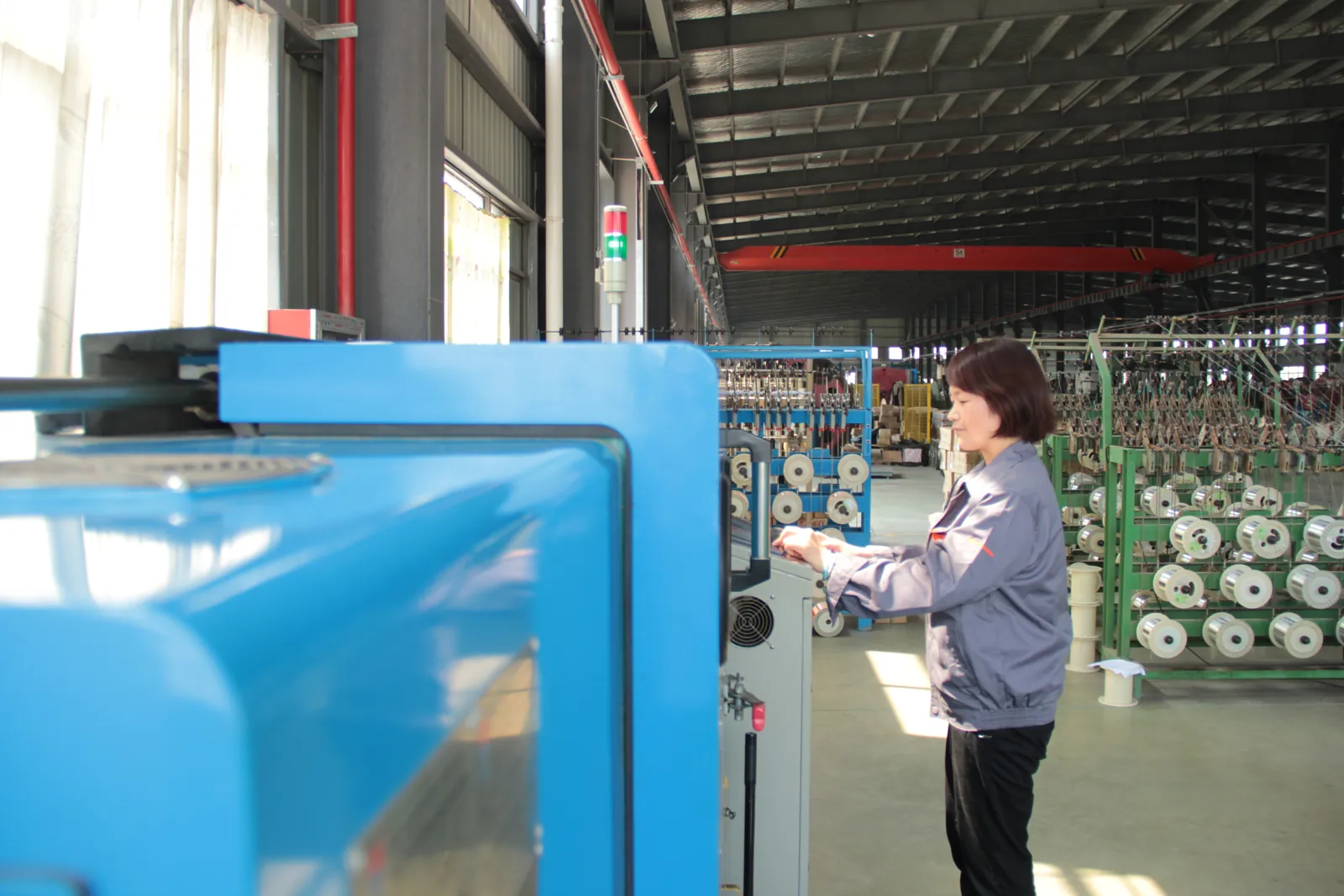
Stranding, insulation extrusion, core assembly and sheathing run under recorded process parameters.
- Class 5/6 stranding with lay length and tension monitored for trailing and reeling flexibility
- Continuous-vulcanisation extrusion with wall thickness and spark tests logged on every length
- Operators sign off each stage before the cable moves to the next machine
Electrical Testing
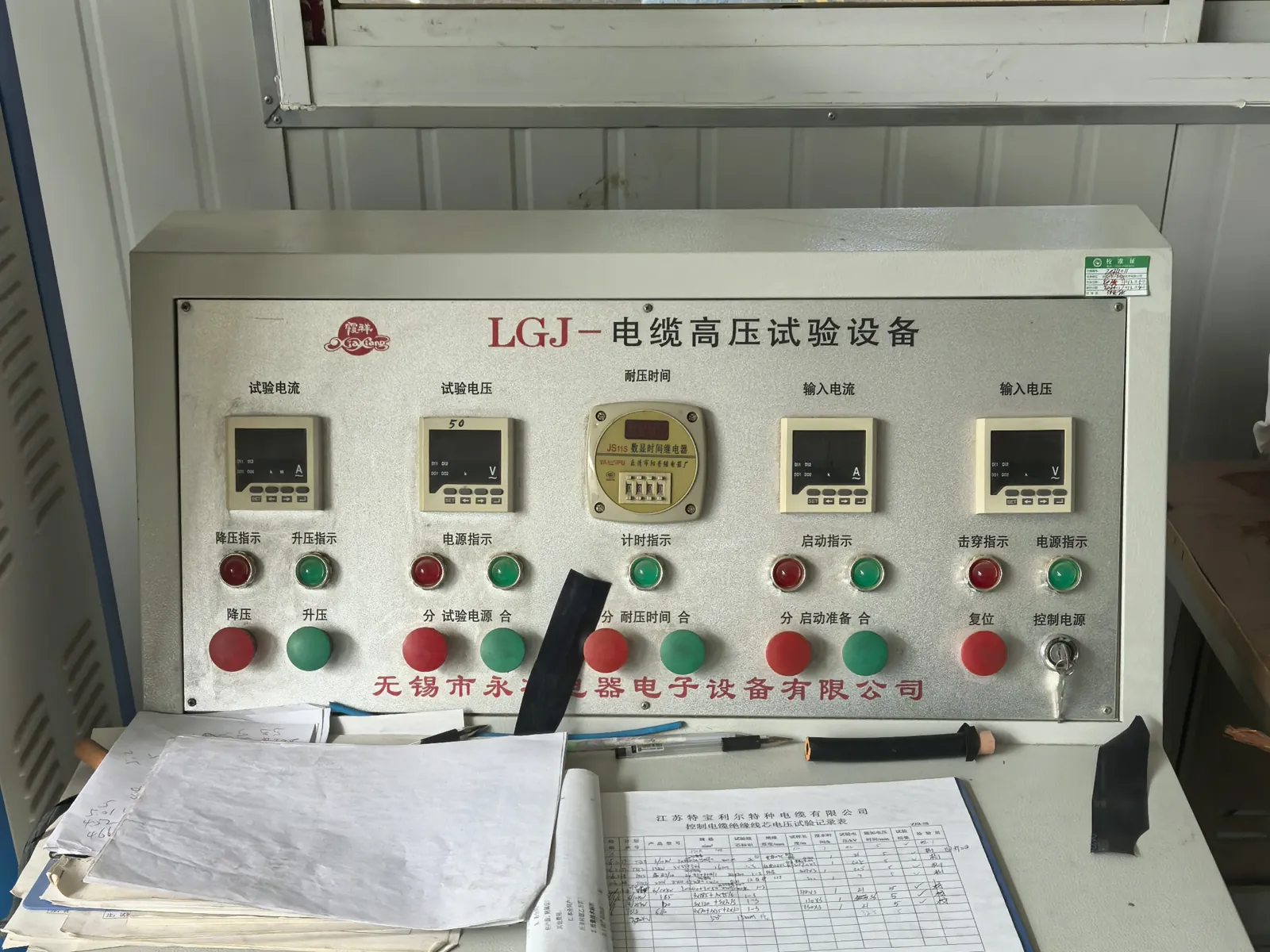
Finished lengths go through the routine tests required by the referenced VDE, ICEA, IEC or NEK standard.
- Conductor resistance and insulation resistance on every length
- Voltage withstand (3.5 kV and higher) and partial-discharge measurement in the shielded HV laboratory
- Screen and pilot-core continuity checks for mining and reeling constructions
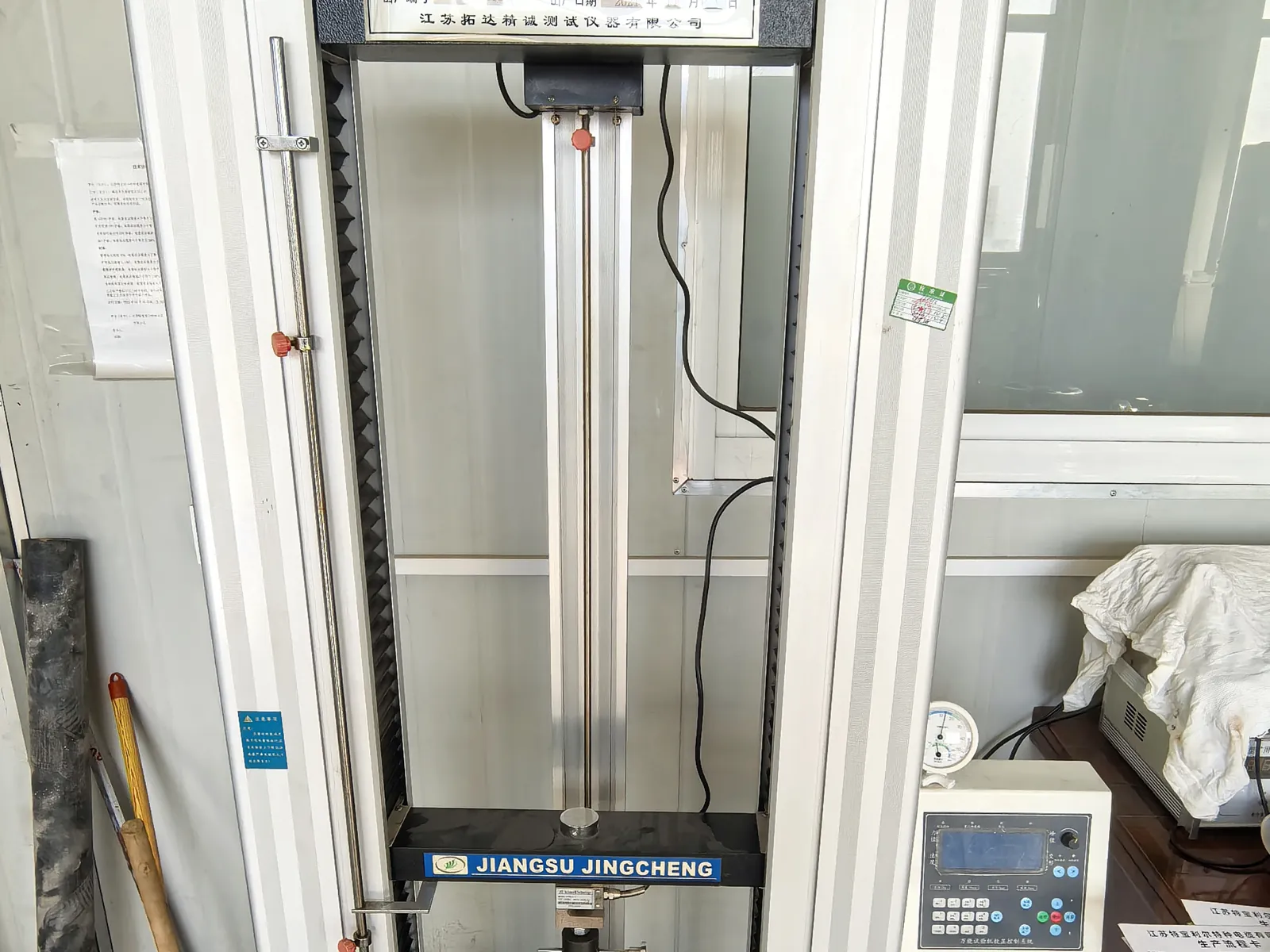
Mechanical and Ageing Tests
Samples from production are tested for the duty a mining, crane or submersible cable will actually see.
- Tensile strength and elongation of insulation and sheath before and after ageing
- Hot-set, ozone, oil-immersion and low-temperature bending tests
- Constant-temperature water bath for insulation resistance of submersible constructions
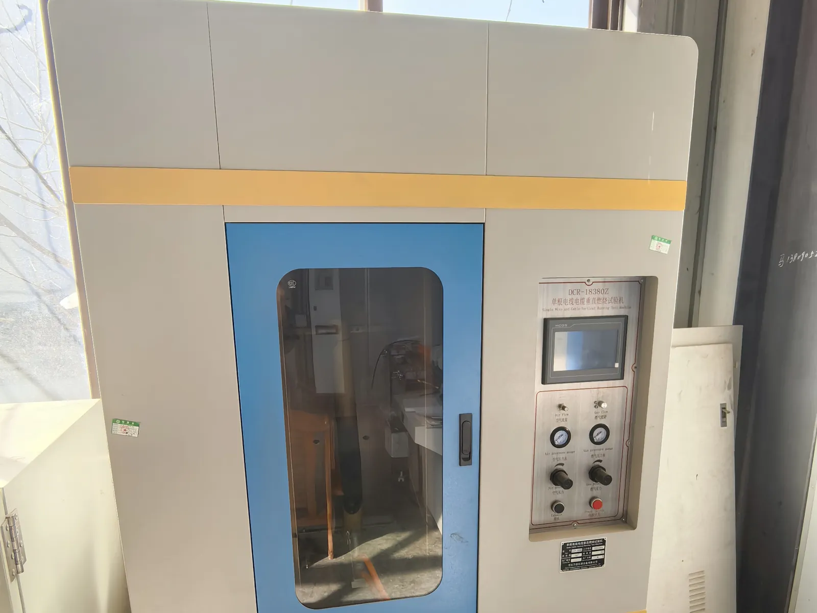
Flame Test and Final Inspection
Before packing, the cable is checked against the order and the flame-performance requirement of its standard.
- Single-cable vertical flame test to IEC 60332-1-2 where specified
- Metre marking, printing, drum length and appearance inspection
- Test report and packing list issued with every shipment
Related products
-
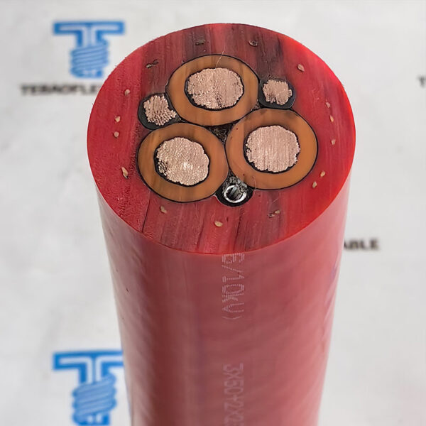
3.6-30kV R-(N)TSCGEWÖU for open-cast mines cable
-
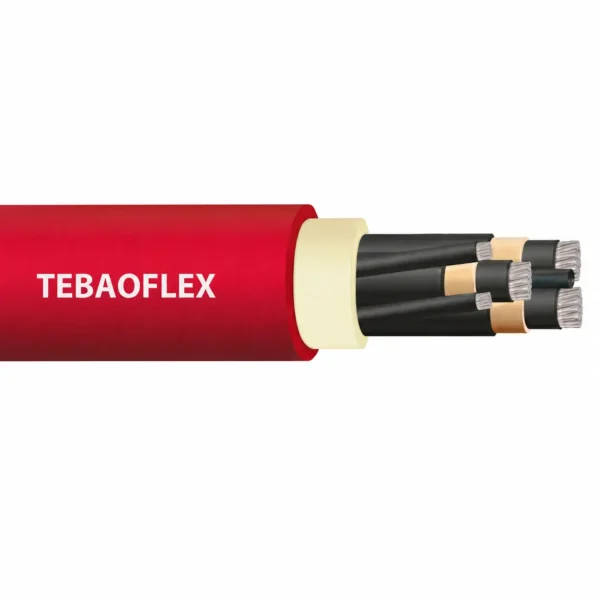
NTSCGECWOEU Coal Cutter Cable VDE 0250 Mining Cable
-
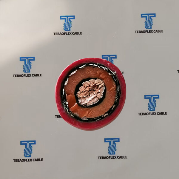
NTMCGCWOEU / (N)TMCGCWOEU 6-30kV Single-Core EPR Heavy-Duty Rubber Cable
-
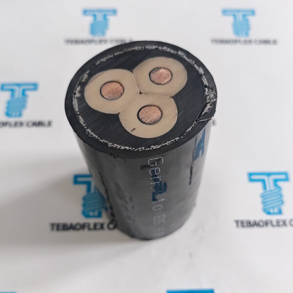
NTSCGECEWOU (N)TSCGECEWÖU Submersible ABT FO Mining Cable
-
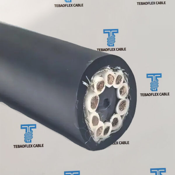
NTMTWOEU Mine Hoist Cable Manufacturer | Underground Mining Lift Cable
-
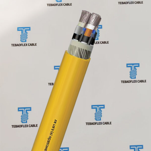
0.6/1kV NSSHCGEÖU(V) Mining Cable 3×70, 3×95, 3×120, 3×150
-
(N)TMCGCW11Y Cable | Medium Voltage Flexible Reeling Cable
-
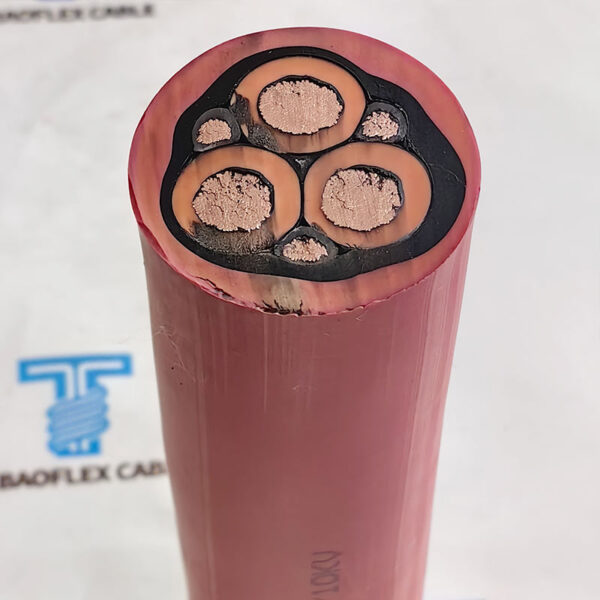
Open-Cast Mining NTSCGEWOEU W 3E Cable in Water & Trailing
Need Pricing for This Cable?
Tell us the length, cores, cross-section and delivery country and we will reply with a quotation and datasheet.